Transmitting arrangement, receiving arrangement, transceiver and method for operation of a transmitting arrangement

a technology of transmitting arrangement and receiving arrangement, which is applied in the direction of transmission, multiple-port network, waveguide-type devices, etc., can solve the problems of reducing efficiency, increasing the overall power consumption of the entire circuit, and reducing the performance of the corresponding componen

Active Publication Date: 2009-03-10
APPLE INC
View PDF24 Cites 49 Cited by
  • Summary
  • Abstract
  • Description
  • Claims
  • Application Information

AI Technical Summary

Benefits of technology

[0012]One aspect of the invention is to reduce the number of standardized 50 ohm interfaces within the various assemblies of the transmitting and receiving arrangement. This is achieved by means of a functional unit comprising radio-frequency antennas and power amplifiers in a transmission path. This contains integrated control for the input impedance of the radio-frequency antenna arrangement. The transmitting arrangement is in this case designed such that an internal output impedance of the power amplifier is directly matched to an input impedance of the radio-frequency antenna arrangement. The circuit impedances of the power amplifier are thus directly matched to the input impedances of the antenna apparatus without having to carry out any transformation to more than 50 ohms by means of additional transformation circuits. This matching is carried out by means of a controllable matching apparatus, which is connected between the output of the power amplifier and the at least one connection of the radio-frequency antenna arrangement.
[0014]Furthermore, the transmitting arrangement and the receiving arrangement contain a matching circuit for frequency matching of the radio-frequency antenna arrangement. The matching circuit in this case has at least one tuning element which can be coupled to the tuning connection of the radio-frequency antenna arrangement. The at least one tuning element is coupled to the tuning connection of the radio-frequency antenna arrangement as a function of a tuning signal at a control input. Depending on the position of the tuning element, the radio-frequency antenna arrangement is thus switched between one of two resonant frequencies. The tuning circuit thus makes it possible to change a resonant frequency of the radio-frequency antenna arrangement in the transmitting arrangement and in the receiving arrangement. The bandwidth of the radio-frequency antenna arrangement that is used in the transmitting arrangement and in the receiving arrangement is thus considerably widened. The impedance change which results from this in the event of a change in the resonant frequency of the radio-frequency antenna arrangement can be compensated for by means of a controllable matching apparatus, thus reducing any mismatch. A single very broadband antenna can thus preferably be used for a number of different mobile radio standards. Controlling the matching of the power amplifier to the radio-frequency antenna arrangement in the transmitting arrangement and of the radio-frequency antenna arrangement to the input of the filter device in the receiving arrangement during operation means that there is no longer any need for transformation to a standardized interface. This also avoids additional power losses caused by the transformation process. Furthermore, costs and space can be saved, resulting from propagation by means of a single broadband multifunctional antenna.
[0016]In one embodiment of the transmitting arrangement, the arrangement has a measurement apparatus for detection of any mismatch between the matching apparatus and the output of the power amplifier. The measurement apparatus is in this case designed to emit a parameter that is derived from this mismatch to an input of the control device. The control device produces the matching signal for the matching apparatus as a function of the applied parameter, in order to compensate for the mismatch. This makes it possible to compensate for dynamic changes in the matching, which are caused, for example, by external environmental influences on the radio-frequency antenna arrangement. In particular, the transmitting arrangement according to the invention is independent of the antenna that is used and of the type of casing containing the transmitting arrangement.
[0020]The method makes it possible to form a functional unit of a transmitting arrangement whose individual component impedances are optimally matched to one another. Impedance changes are corrected. The functional unit is particularly flexible and is independent of external influences changing the impedances. The standardized transformation process to a fixed value that has been carried out until now can thus be omitted. Furthermore, if the method according to the invention is carried out continuously, the power consumption and the efficiency of the power amplifier are independent of the external influences which change the antenna impedance. This makes it possible to produce very broadband antennas in the arrangement.

Problems solved by technology

Outside these frequency ranges, matching errors result in losses, which considerably reduce the performance of the corresponding component.
This increases the overall power consumption of the entire circuit, reduces the efficiency, and increases the production costs.

Method used


Image

  • Transmitting arrangement, receiving arrangement, transceiver and method for operation of a transmitting arrangement
  • Transmitting arrangement, receiving arrangement, transceiver and method for operation of a transmitting arrangement
  • Transmitting arrangement, receiving arrangement, transceiver and method for operation of a transmitting arrangement

Examples


Embodiment Construction

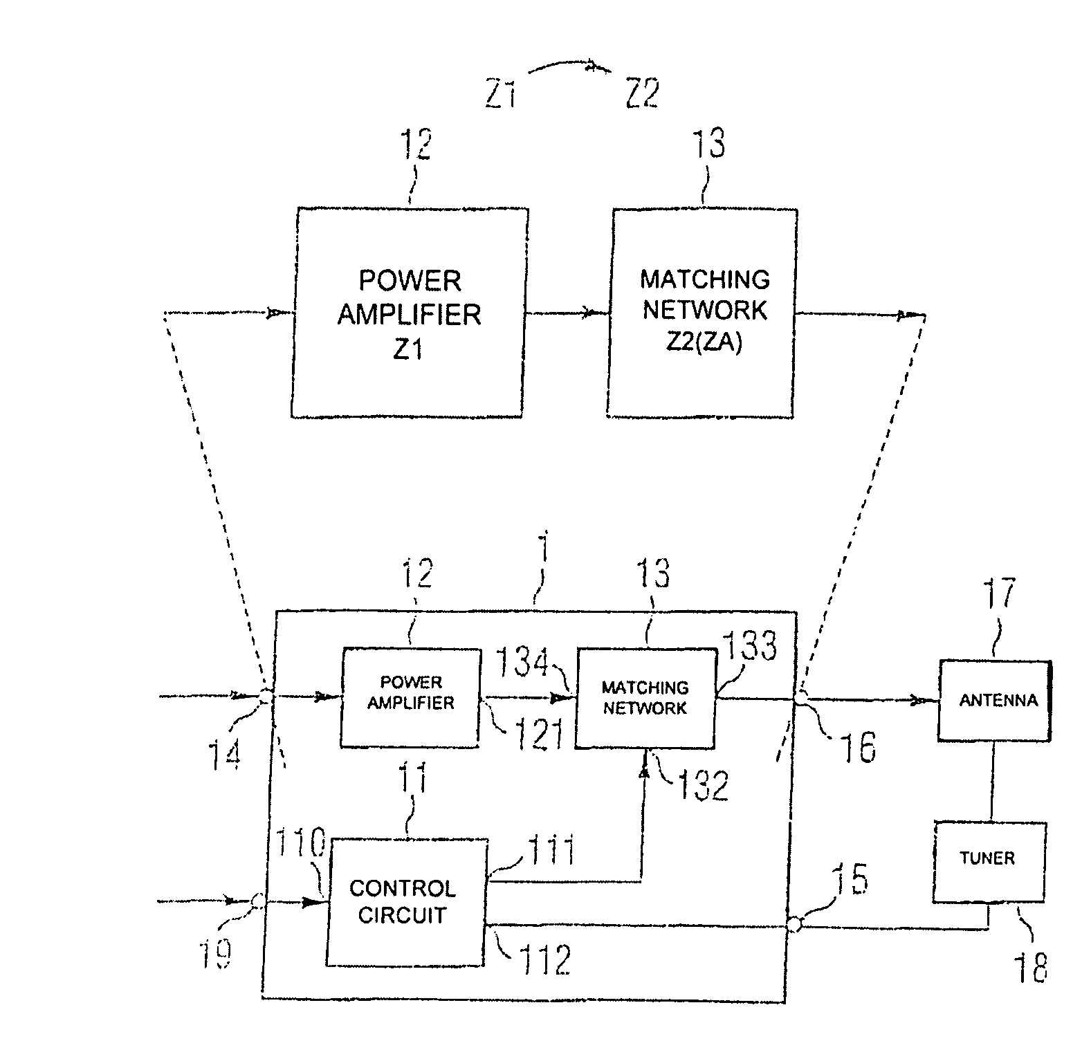
[0030]FIG. 1 shows an exemplary embodiment of a transmitting arrangement according to the invention. This transmitting arrangement can be implemented in particular in mobile communication appliances which are designed for transmission of signals on the basis of different mobile radio standards. The transmitting arrangement according to the invention is integrated in a mobile communication appliance which is designed to transmit signals on the basis of the GSM Standard or on the basis of the WCDMA Standard. Both mobile radio standards transmit and receive on different frequencies. GSM transmits in the range between 800 MHz and 1.9 GHz, with signals based on the WCDMA Standard being transmitted and received in the region of 2.1 GHz. The bandwidth or frequence range of the signals to be transmitted may thus cover several 100 MHz. In consequence, it is necessary to provide a very broadband antenna for the transmitting arrangement according to the invention.

[0031]As can be seen in the ex...


PUM


Abstract

In a transmitting arrangement a power amplifier is coupled to a radio-frequency antenna arrangement via a controllable matching apparatus. This allows direct impedance transformation of the output of the power amplifier to the input of the radio-frequency antenna arrangement. There is no need for transformation to the 50 ohm standard. The power amplifier, matching apparatus and a control circuit for controlling the impedance of the matching apparatus form a functional unit, which is advantageously in the form of a monolithically integrated structure in a semiconductor body. A receiving arrangement is produced in the same way, comprising an antenna, a filter device and a matching apparatus connected between them.

Description

REFERENCE TO RELATED APPLICATIONS[0001]This application claims the benefit of the priority date of German application DE 10 2004 026 133.4, filed on May 28, 2004, the contents of which are herein incorporated by reference in their entirety.FIELD OF THE INVENTION[0002]The invention relates to a transmitting arrangement, a receiving arrangement, and a transceiver having such a transmitting arrangement and receiving arrangement. The invention also relates to a method for operation of a transmitting arrangement.BACKGROUND OF THE INVENTION[0003]Modern cellular telephones require ever higher data transmission rates and different mobile radio standards. While the GSM mobile radio standard already provides adequate data transmission rates for speech data transmission, the WCDMA / UMTS mobile radio standard is required for transmission of greater amounts of data. The W-LAN (Wireless Local Area Network) is used for very high data transmission rates, for example, for multimedia applications. Owi...

Claims


Application Information

Patent Timeline
Patent Type & Authority Patents(United States)
IPC IPC(8): H04B1/04H04B1/40H01Q1/32H04B1/16H04B1/18
CPCH04B1/0458H04B1/18
Inventor KRONBERGER, RAINERHEBERLING, DIRKGEISSLER, MATTHIASMULLER, JAN-ERIK
Owner APPLE INC
Why Eureka
Try Eureka