Elevator safety circuit monitoring system and method

a safety circuit and monitoring system technology, applied in the field of elevator safety circuit monitoring system and method, can solve the problems of avoiding the need for galvanic connection or other difficult changes to the safety circuit, unnecessary cables, etc., to ensure safe operation of the elevator, facilitate the monitoring of the condition of the elevator, and ensure the safety level of the elevator

Active Publication Date: 2009-03-17
KONE CORP
View PDF11 Cites 14 Cited by
  • Summary
  • Abstract
  • Description
  • Claims
  • Application Information

AI Technical Summary

Benefits of technology

[0011]In an embodiment of the invention, the intensity of the current flowing in the safety circuit is measured by means of a Hall current sensor galvanically separated from the safety circuit. The Hall current sensor measures the magnetic field generated by the current flowing in the safety circuit, and thus the safety circuit itself need not be touched at all in order to obtain a reliable measurement result. This obviates the need to make any galvanic connections or other difficult changes to the safety circuit. The Hall sensor can be connected to the safety circuit without interrupting the wiring of the safety circuit.
[0016]It is an objective of the invention is to measure the state of the safety circuit in such a way that no changes and no galvanic connections of any sort need to be made to the safety circuit. Thus, no extra load is imposed on the safety circuit. It is also an objective of the invention to define the state of the safety circuit for an analyzer estimating the condition of the elevator and forming an important part of the condition monitoring equipment of an elevator already in use. In this way it is possible to facilitate the monitoring of the condition of the elevator and to guarantee safe operation of the elevator.
[0017]The present invention has several advantages as compared to prior-art solutions. The invention makes it possible to determine the state of the safety circuit and the position of each safety switch. Based on different states of the safety circuit, it can be inferred whether the elevator is working in accordance with the requirements imposed on it as it is moving from floor to floor. The invention also provides reliable information as to whether the safety circuit is functioning in accordance with the requirements set on it.
[0018]By applying the procedure disclosed in the invention, a sufficient safety level of an elevator can be guaranteed by monitoring the state of the safety circuit without making any galvanic connections or other changes to the sensitive safety circuit. The system of the invention for monitoring the state of the safety circuit can also be easily installed as a retrofit on elevators already in use.

Problems solved by technology

This obviates the need to make any galvanic connections or other difficult changes to the safety circuit.
This makes it unnecessary to provide cables between the elevator car and the machine room.

Method used


Image

  • Elevator safety circuit monitoring system and method
  • Elevator safety circuit monitoring system and method
  • Elevator safety circuit monitoring system and method

Examples


Embodiment Construction

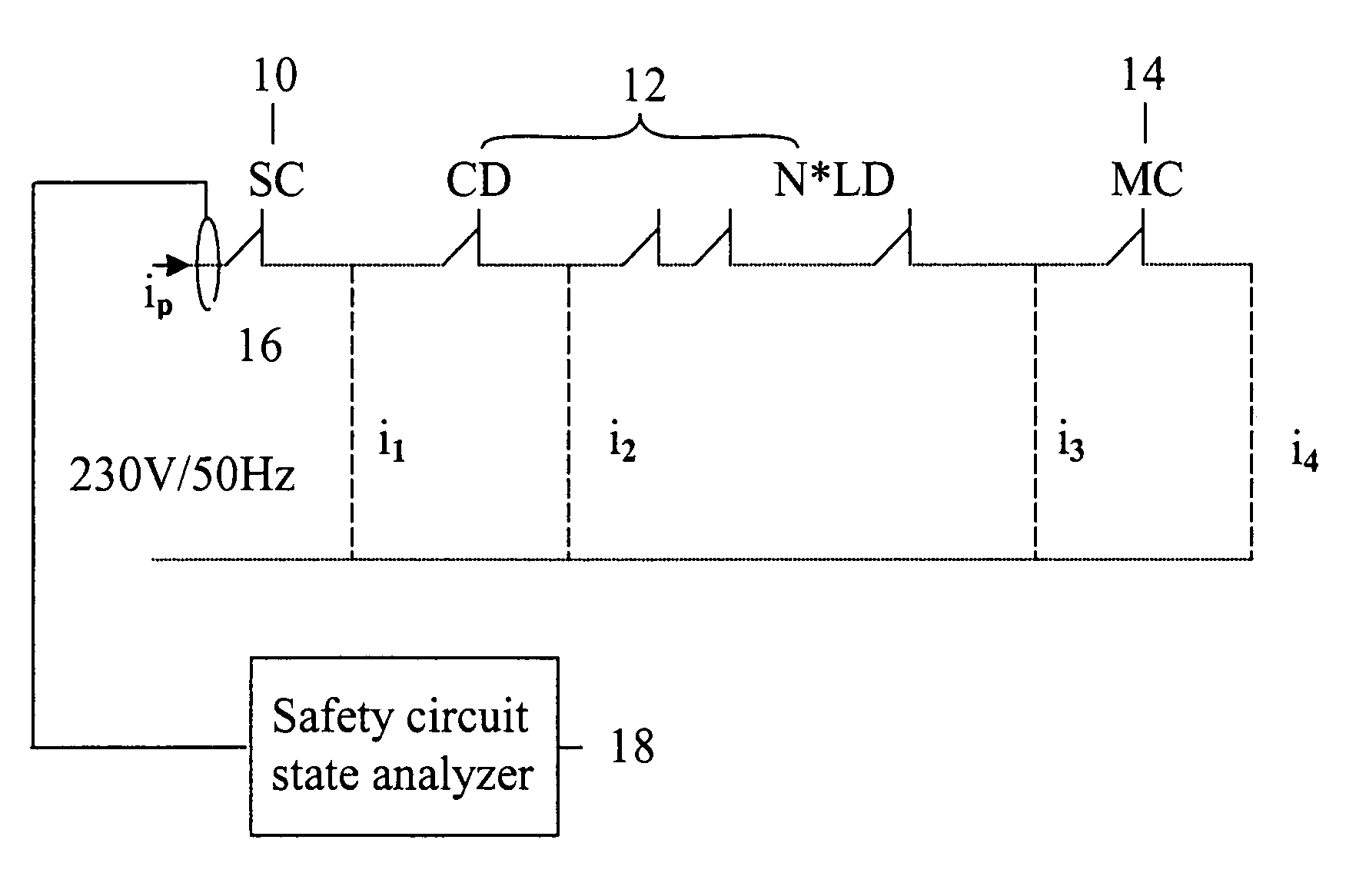
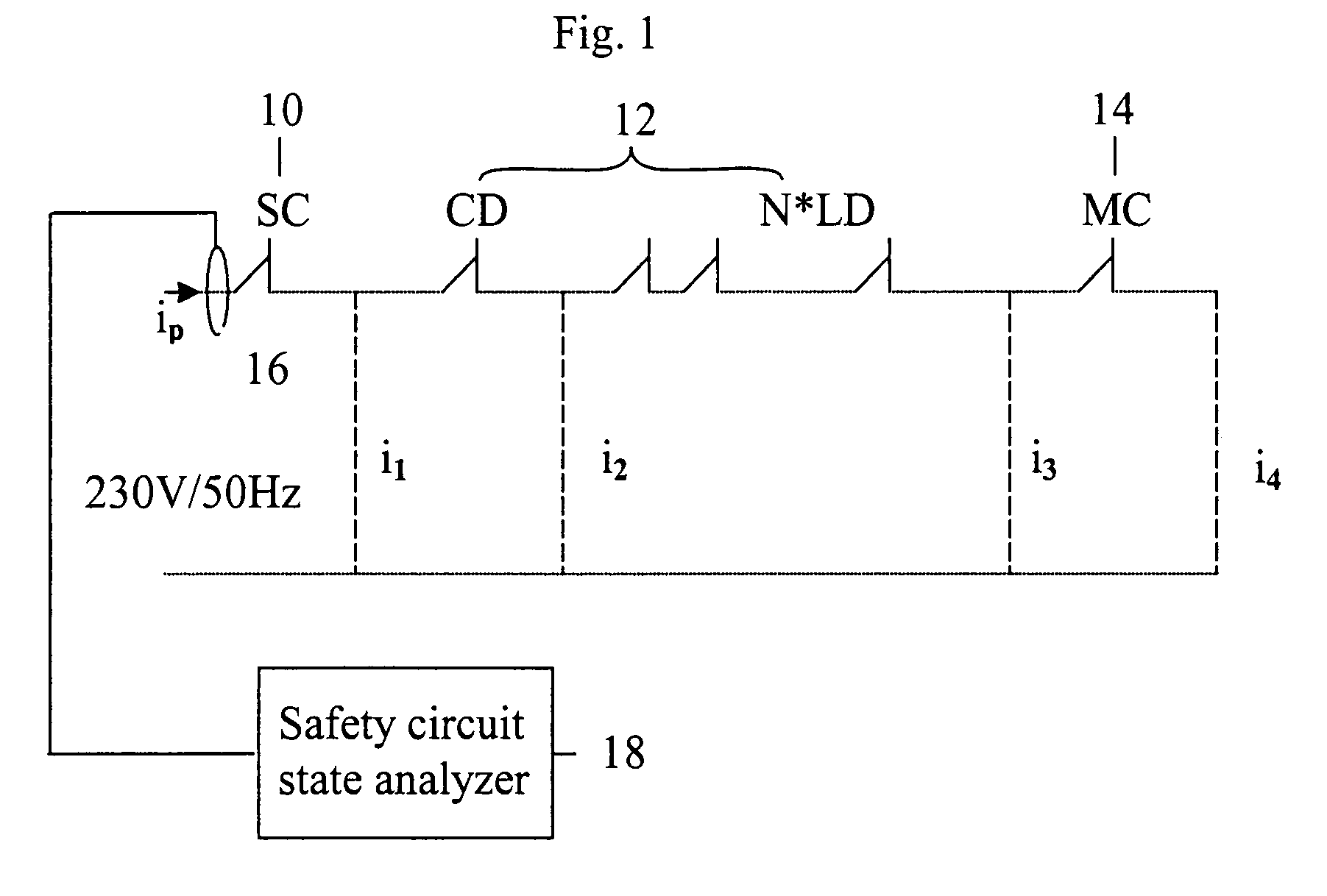
[0026]In the following, the invention will be described in detail with reference to FIGS. 1-4. FIG. 1 presents a safety circuit with the safety circuit currents i1, i2, i3 and i4 indicated according to the invention at different points in the circuit.

[0027]In the safety circuit presented in FIG. 1, SC 10 represents the static circuit of the safety circuit. Switch CD 12 represents the car door switch, and switches N*LD 12 represent the landing door switches. The number of levels is N, depending on how many floors the elevator comprises. Switch MC 14 corresponds to the main contactor.

[0028]The total current ip at point p is obtained as follows:

[0029]ip=SC·i1+CD·i2+i3·∏k=1N⁢LDk+MC·i4,

where switches SC, CD, LD and MC get the value of 0 or 1.

[0030]From the magnitude of the total current, the state of the safety circuit at each instant of time can be unambiguously deduced. The possible states of the safety circuit are defined in Table 1 below:

[0031]

TABLE 1Safety circuitcurrent atOperation...


PUM


Abstract

The invention concerns a method and a system for monitoring the operation of the safety circuit of an elevator, said safety circuit containing safety switches connected in series with a contactor and a static circuit. In the method, the current flowing in the safety circuit is measured and the state of the safety circuit is determined on the basis of the measured current. The measurement of the safety circuit current is preferably performed without a galvanic connection to the safety circuit. The state of the safety circuit is determined on the basis of the magnitude of the measured current, from which the positions of the safety switches during the current measurement can be inferred.

Description

This application is a Continuation of copending PCT International Application No.[0001]PCT / FI2006 / 000084 filed on Mar. 10, 2006, which designated the United States, and on which priority is claimed under 35 U.S.C. §120. This application also claims priority under 35 U.S.C. § 119(a) on Patent Application No(s). 20050361 filed in Finland on Apr. 8, 2005. The entire contents of each of the above documents is hereby incorporated by reference.FIELD OF THE INVENTION[0002]The present invention relates to elevator systems. In particular, the present invention concerns a method and a system for monitoring the operation of a safety circuit in elevator systems.BACKGROUND OF THE INVENTION[0003]It is of primary importance for the operation of an elevator system that the system should work correctly and above all safely.[0004]For this reason, elevator systems employ a number of different safety devices. One of these is the so-called safety circuit. The safety circuit is the most important part of...

Claims


Application Information

Patent Timeline
Patent Type & Authority Patents(United States)
IPC IPC(8): B66B1/34B66BB66B5/00B66B13/22
CPCB66B5/0031B66B13/22
Inventor TYNI, TAPIOPERALA, PEKKA
Owner KONE CORP
Why Eureka
Try Eureka