Gantry crane

a crane and gantry technology, applied in cranes, braking devices for hoisting equipment, railway tracks, etc., can solve the problem that the top of the legs provide limited flexibility for accommodating the floor, and achieve the effect of easy erection

Inactive Publication Date: 2009-03-17
PETRICIO YAKSIC DAVOR
View PDF17 Cites 22 Cited by
  • Summary
  • Abstract
  • Description
  • Claims
  • Application Information

AI Technical Summary

Benefits of technology

[0004]The new gantry crane is transportable in sections and is easily erected and bolted together at five points. The crane is strong and rig...

Problems solved by technology

The vertical plates at the top of the legs provide limit...

Method used


Image

  • Gantry crane
  • Gantry crane
  • Gantry crane

Examples


Embodiment Construction

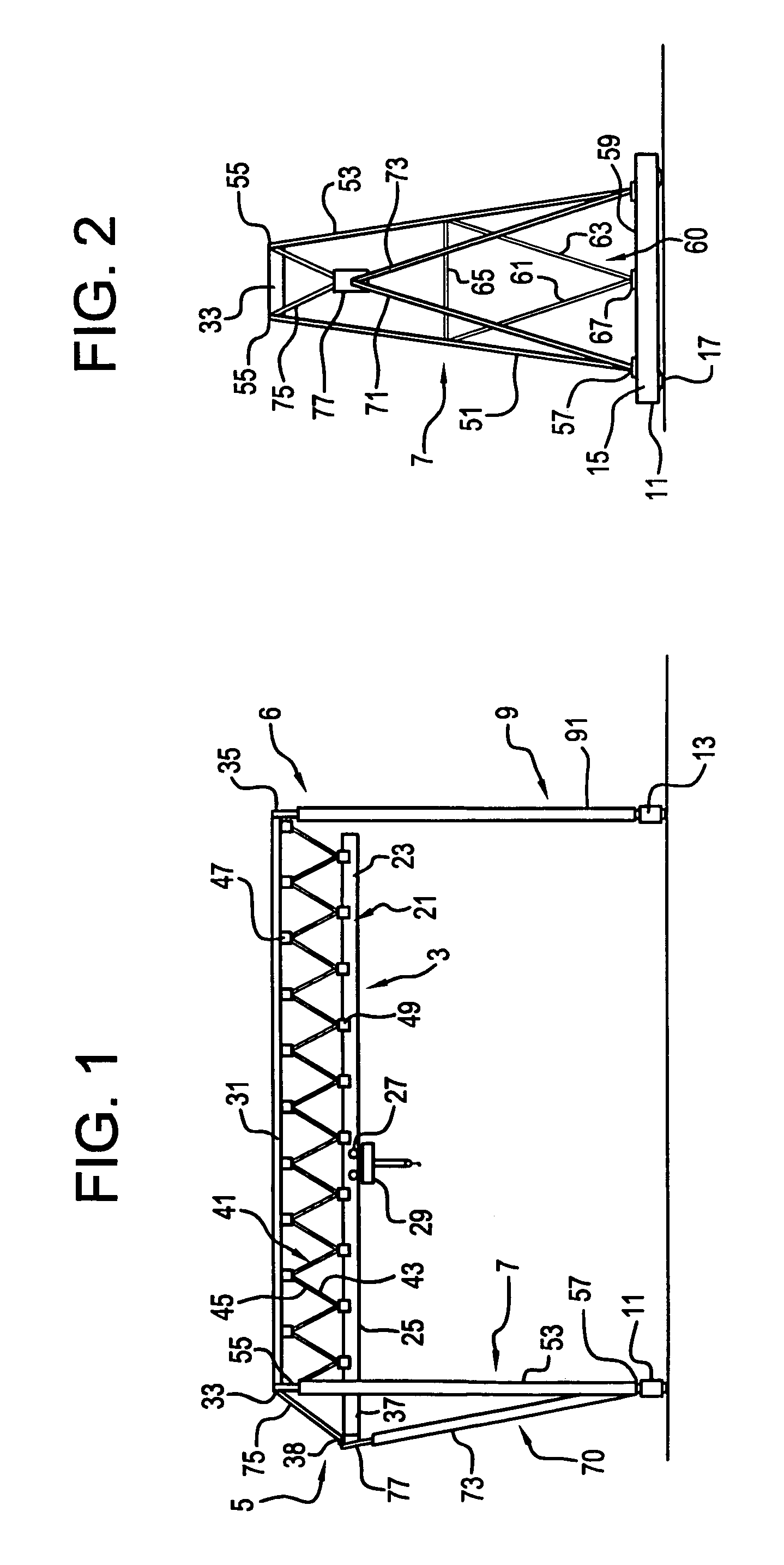
[0034]The gantry crane of the invention is generally indicated by the numeral 1. The gantry crane has an upper open truss three-dimensional cross-beam generally referred to by the numeral 3. The beam 3 is supported rigidly at a first end 5 by a rigid leg structure 7. A second end 6 of beam 3 is supported by vertical support legs 9. Carriages 11 and 13 are connected to the bottoms of rigid support legs 7 and to the bottoms of vertical support legs 9, respectively. The carriages have axles 15 and wheels 17, at least some of which are driven, preferably by synchronous motors, frequency motors or stepping motors to assure that the carriages move together when on tracks. Because of the unique construction, if one motor fails, the remaining motor or motors may move the crane successfully.

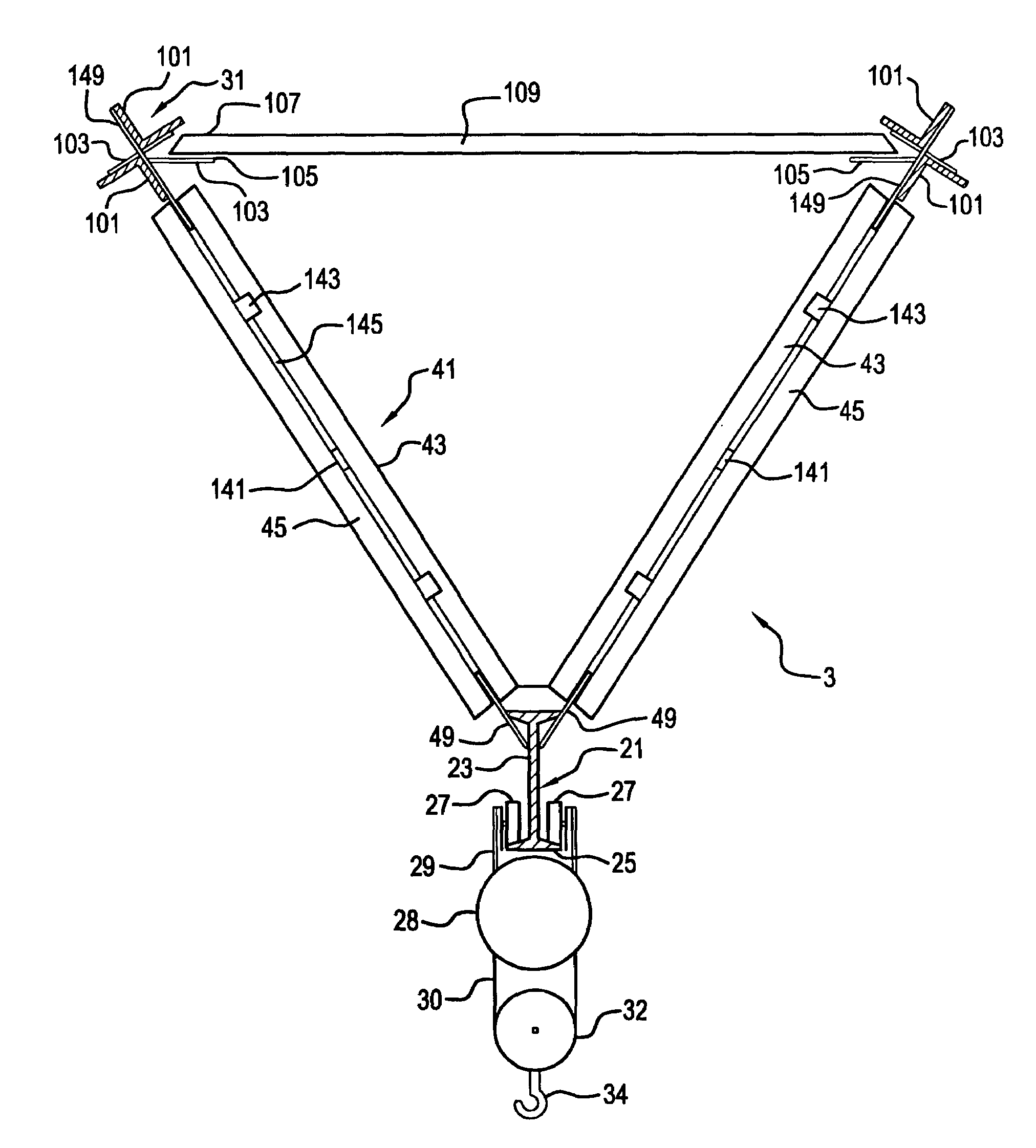
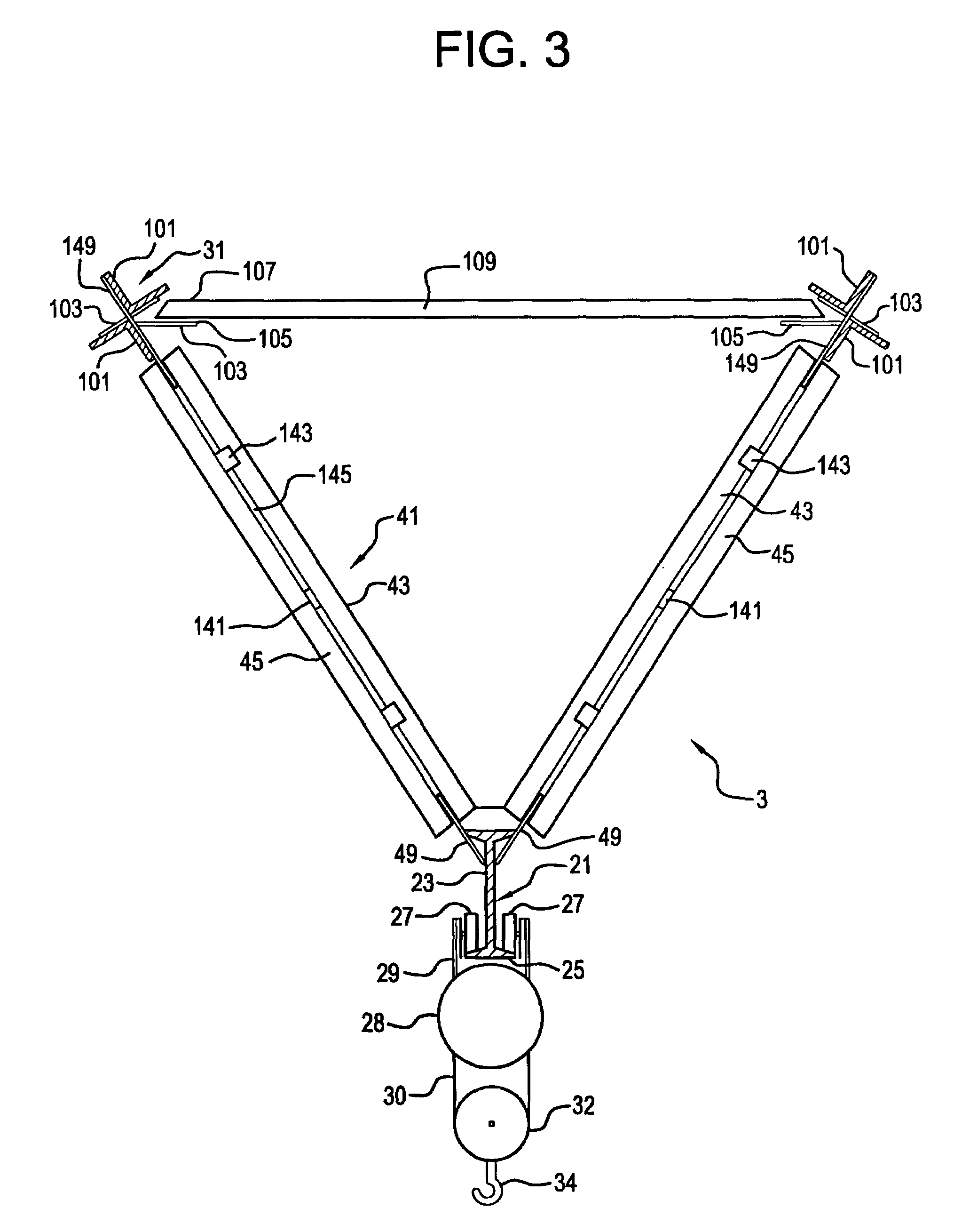
[0035]The three-dimensional open beam 3 has a lower member 21, which is preferably an I-beam with a vertical web 23 and lower oppositely extending flanges 25, on which wheels 27 of a trolley 29 ride. Beam...


PUM


Abstract

A gantry crane has a rigid open three-dimensional truss cross-beam. A lower I-beam and parallel upper X-beams are interconnected with angular gussets and angle irons forming a triangular open beam bounded by three trusses. Angular gussets on the sides are as parallel members to provide maximum strength. One end support is rigid, with upper ends of legs having plates bolted to one end plate extending between the X-beams. Outrigger legs have an upper plate bolted to a sloped plate at an extended end of the I-beam. Vertical support legs at the other end have a strengthening cross-member and upper vertical plates which are bolted to the end plate on the X-beams. The unusual cross-beam structure and the unusual rigid leg structure and rigid interconnection provide rigidity of the entire crane. The vertical support legs accommodate variations in tracks.

Description

BACKGROUND OF THE INVENTION[0001]Gantry cranes are widely used throughout the world to move heavy equipment within warehouses and storage yards and to load and unload freight vehicles. The gantry cranes have overhead beams on which trolleys with cable winders, sheaves and hooks ride on wheels from side to side to raise, lower and laterally move loads. Carriages are usually provided at the bottoms of legs which support the beams. The carriages move the gantry cranes along a floor or on tracks to approach, lift, reposition and deposit loads as cable winders on the trolleys are activated and the carriages are moved.[0002]Existing gantry cranes are cumbersome and are difficult to move between locations, and cranes are heavy and are difficult to transport to locations and to erect at the locations because of the great weight that is required to provide the strength of the cranes. Lightweight cranes are unsuited for lifting significant loads.[0003]Needs exist for new and improved gantry c...

Claims


Application Information

Patent Timeline
IPC IPC(8): B66C5/02B66C17/00B66C19/00
CPCB66C5/02B66C6/00
Inventor PETRICIO YAKSIC, DAVOR
Owner PETRICIO YAKSIC DAVOR
Why Eureka
Try Eureka