Coin arranging/conveying apparatus

a technology for arranging/conveying equipment and coins, which is applied to coin counters, coin/paper handlers, instruments, etc., can solve the problems of prone to wear of the arranging/conveying belt, large differences in the size of coins in foreign currencies, and the above-mentioned coin arranging/conveying equipment may be prone to problems, so as to achieve reliable transportation and reliable execution of further processing.

Inactive Publication Date: 2009-03-17
GLORY KOGYO KK
View PDF2 Cites 4 Cited by
  • Summary
  • Abstract
  • Description
  • Claims
  • Application Information

AI Technical Summary

Benefits of technology

[0009]The first gate portion is defined by the separation roller, the portion of the arranging / conveying surface of the arranging / conveying belt that faces the separation roller, and the movable roller facing the underside of the arranging / conveying surface of the arranging / conveying belt. The second gate portion is defined by the coin passage upstream end roller, the portion of the arranging / conveying surface of the arranging / conveying belt that faces the coin passage upstream end roller, and the portion of the transfer belt wrapped around the coin passage upstream end roller. Coins can be arranged in a single layer in single file by means of the first gate portion, as well as the second gate portion. Therefore, the present invention ensures reliable transportation of coins one at a time through the first gate portion and the second gate portion into the coin passage unit even if there is a great difference in diameter or thickness of coins. Furthermore, at the first gate portion, the movable roller is capable of coming into contact with the underside of the arranging / conveying belt, which faces away from the arranging / conveying surface, so that the movable roller rotates together with the movement of the arranging / conveying surface of the arranging / conveying belt. With the configuration as above, the contact area of the movable roller with the arranging / conveying surface is minimized so that both are less prone to wear.
[0010]According to another feature of the present invention, wherein the movable roller, which is adapted to move downward should an excessively thick coin or a plurality of coins overlapping each other forming an excessive thickness enter the first gate portion, is attached to a first arm that is capable of tilting around a first supporting shaft; a conveyance width control member for reducing the width of the passage for conveying coins to the second gate portion is provided at one of the widthwise sides of the portion of the arranging / conveying belt that extends from the first gate portion into the second gate portion; and the aforementioned conveyance width control member is attached to a second arm adapted to tilt around a second supporting shaft in conjunction with the tilting motion of the first arm so that the conveyance width control member descends together with the descent of the movable roller.
[0011]The invention facilitates transportation of coins one at a time to the second gate portion, because the width of the passage in which coins are conveyed to the second gate portion is reduced by the conveyance width control member, which is provided along a side edge of the portion of the arranging / conveying belt from the first gate portion into the second gate portion.
[0013]The invention ensures reliable transportation of coins one at a time into the coin passage unit by means of the first transfer belt member and the second transfer belt member. The coin arranging / conveying apparatus of the present invention also ensures reliable execution of further processing of the coins by enabling each coin to be conveyed in such a state that ensures its rim is pressed against the slanted directing portion and the coin rim control portion of the passage side plate.

Problems solved by technology

However, coins in foreign currencies may present a great difference in size; in some countries, the largest coin may have twice the diameter or thickness of the smallest coin.
Should there be such a great difference in diameter or thickness, the coin arranging / conveying apparatus described above may be prone to a problem of coins being caught in the gate portion.
Nevertheless, as the arranging / conveying belt is constantly moving while the movable guide does not move in the conveying direction, the arranging / conveying belt is prone to wear due to contact with the movable guide.
As a result, the coins are prone to become jammed at the stage in which they are conveyed to a transfer belt of the coin passage at the downstream side.

Method used


Image

  • Coin arranging/conveying apparatus
  • Coin arranging/conveying apparatus
  • Coin arranging/conveying apparatus

Examples


Embodiment Construction

[0019]A description is given of an embodiment of the present invention hereunder with reference to the accompanying drawings.

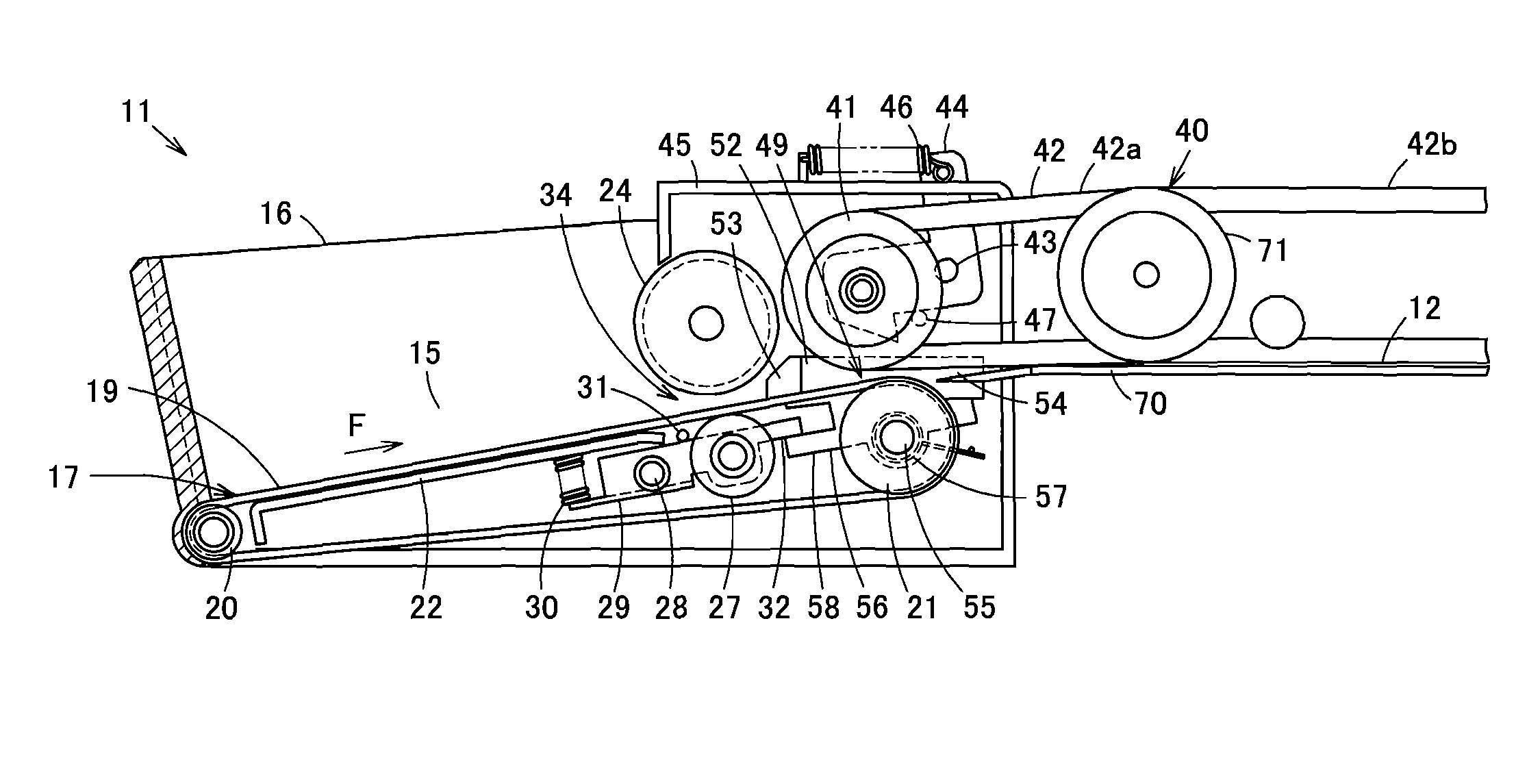
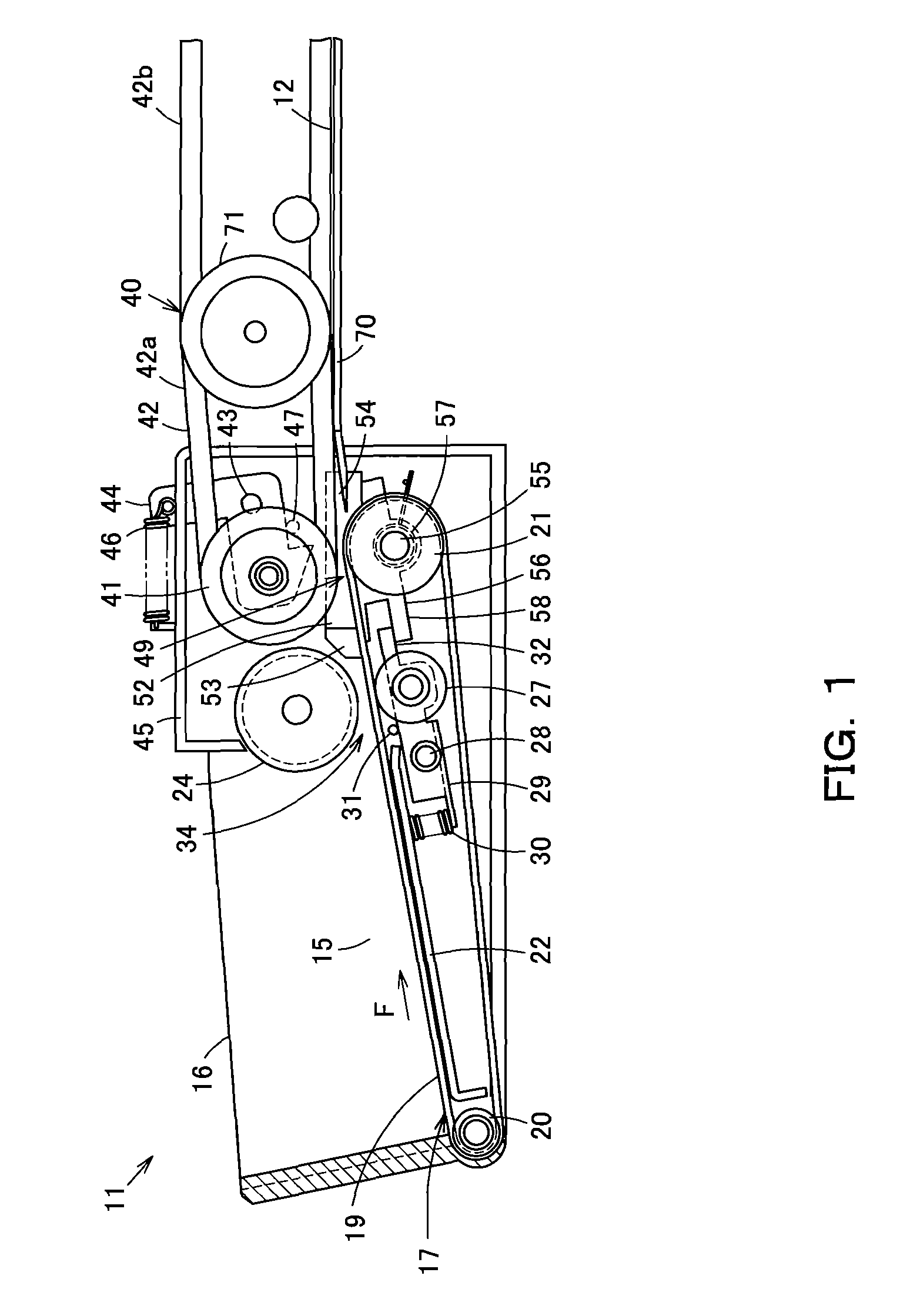
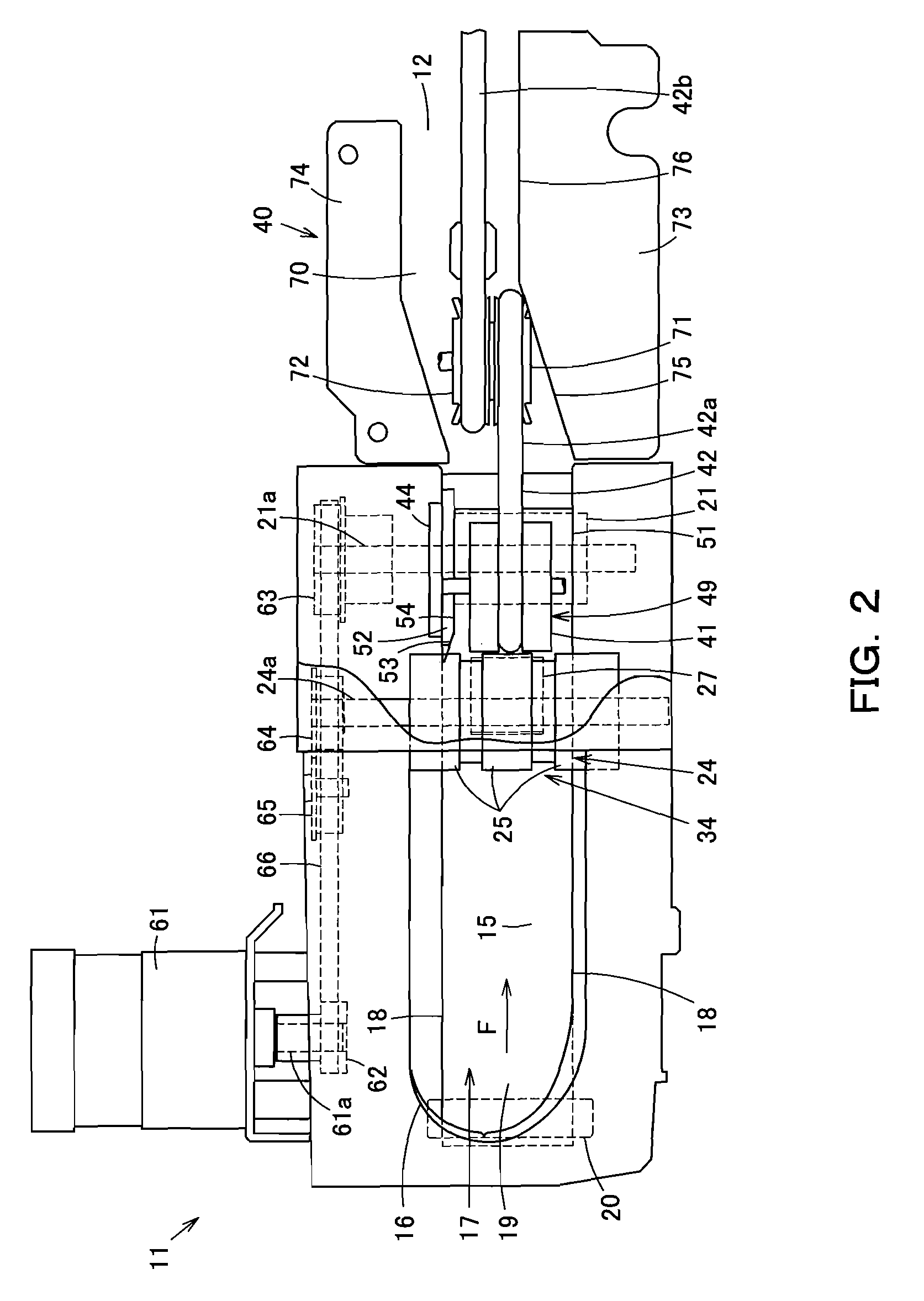
[0020]Referring to FIGS. 1 and 2, a coin arranging / conveying apparatus 11 may be used, for example, in a coin processing apparatus, such as a coin depositing and dispensing machine, to receive a plurality of coins dropped into a receptacle of the coin processing apparatus, separate the received coins, and convey them to a coin passage 12 at the downstream side. While being passed through the coin passage 12, the coins undergo further processing, such as counting at a counting section and sorting at a sorting section.

[0021]The coin arranging / conveying apparatus 11 has a coin hopper 16, which forms a holding portion 15 for receiving and holding coins deposited into the coin arranging / conveying apparatus 11. An arranging / conveying belt 17 for bearing coins thereon and conveying them to the coin passage 12 is disposed at the bottom of the holding portion 15 of the...


PUM


Abstract

The present invention provides a coin arranging / conveying apparatus that is capable of reliably conveying coins one at a time into a coin passage unit even if there is such a great difference in diameter or thickness of coins. A first gate portion is defined by a separation roller, an arranging / conveying surface of an arranging / conveying belt, and a movable roller. The movable roller faces the underside of the arranging / conveying surface of the arranging / conveying belt. A second gate portion is defined by a coin passage upstream end roller, and the portion of a transfer belt wrapped around the coin passage upstream end roller. Coins are arranged in a single layer in single file by means of the first gate portion, as well as the second gate portion.

Description

INCORPORATION BY REFERENCE[0001]The present application claims priority under 35 U.S.C. §119 to Japanese Patent Application No. 2005-284130 filed on Sep. 29, 2005. The content of the application is incorporated herein by reference in its entirety.FIELD OF THE INVENTION[0002]The present invention relates to a coin arranging / conveying apparatus wherein coins retained in a coin hopper are taken out and conveyed by means of an arranging / conveying belt provided at the bottom of the coin hopper, and the coins are arranged in a single layer in single file by means of a gate portion that is provided with a separation roller facing the arranging / conveying belt.BACKGROUND OF THE INVENTION[0003]Conventionally, there is a coin arranging / conveying apparatus that requires taking out and conveying coins by means of an arranging / conveying belt provided at the bottom of a coin hopper, controlling the coins into a single-layer state by means of a gate portion having a separation roller that faces the...

Claims


Application Information

Patent Timeline
Patent Type & Authority Patents(United States)
IPC IPC(8): G07D1/00
CPCG07D9/008
Inventor IWAMI, TOYOFUMIMURANAKA, MITSUHIKO
Owner GLORY KOGYO KK
Why Eureka
Try Eureka