Prosthetic foot

a technology for applied in the field of prosthetic feet and footplates, can solve the problems of large complexity of current designs, and high cost of many current prosthetic feet, and achieve the effect of improving prosthetic feet and low cos

Active Publication Date: 2009-03-17
KAUPTHING BANK
View PDF33 Cites 65 Cited by
  • Summary
  • Abstract
  • Description
  • Claims
  • Application Information

AI Technical Summary

Benefits of technology

[0009]In order to provide low cost and improved prosthetic feet, exemplary embodiments of a prosthetic foot are described.
[0019]The numerous advantages, features and functions of the various prosthetic feet will become readily apparent and better understood in view of the following description, appended claims, and accompanying drawings. The following description is not intended to limit the scope of the prosthetic feet, but instead merely provides exemplary embodiments for ease of understanding.

Problems solved by technology

While the current designs of prosthetic feet and footplates represent an advance over the previous designs, a majority of the current designs have become quite complex.
Due to the complexity of the designs, and material and manufacturing costs, current prosthetic feet are relatively expensive.
Due to the relatively high cost of many current prosthetic feet, people in developing and underdeveloped countries and regions of the world have limited or no access to prosthetic feet and footplates.
This is especially unfortunate, as many underdeveloped and developing regions are recovering from years of civil wars and regional conflicts where the use of landmines has been rampant.
Since landmines have a tendency to cause injuries to the lower extremities, there is a large need for prosthetic feet and footplates in regions that are affected by this danger.
However, most of the people in developing and underdeveloped regions who are in need of prosthetic limbs are precluded access to most of the current designs because of their economic situation.

Method used


Image

  • Prosthetic foot
  • Prosthetic foot
  • Prosthetic foot

Examples


first embodiment

B. Detailed Description of a First Embodiment

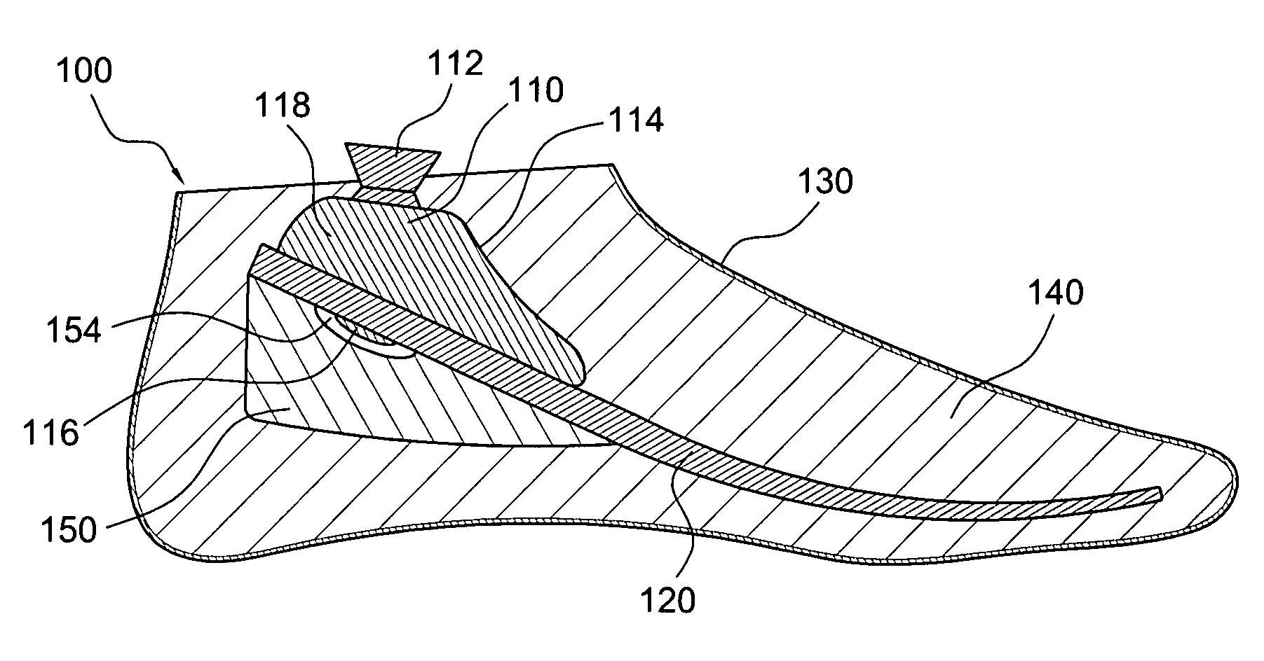
[0034]A first embodiment of a prosthetic foot 100 is shown in FIG. 1. The prosthetic foot 100 is constructed around a resilient footplate 120. The footplate 120 is appropriately shaped and configured to provide load bearing support and prosthetic foot characteristics permitting smooth ambulation.

[0035]Thus, the footplate 120 may be substantially planar, or may include one or more slight or gradual curves. The footplate 120 may include at least one recessed portion or cut out (not shown) in the anterior portion of the footplate 120 in order to provide what is known in the art as a “sandal toe,” which allows a user to wear conventional toe strap sandals on the prosthetic foot, in addition to traditional footwear that covers the entire foot.

[0036]In an exemplary configuration, the footplate 120 may be inclined at an angle of twenty degrees with respect to the supporting surface or ground. Of course, any suitable orientation that provides the...

fourth embodiment

D. Detailed Description of a Fourth Embodiment

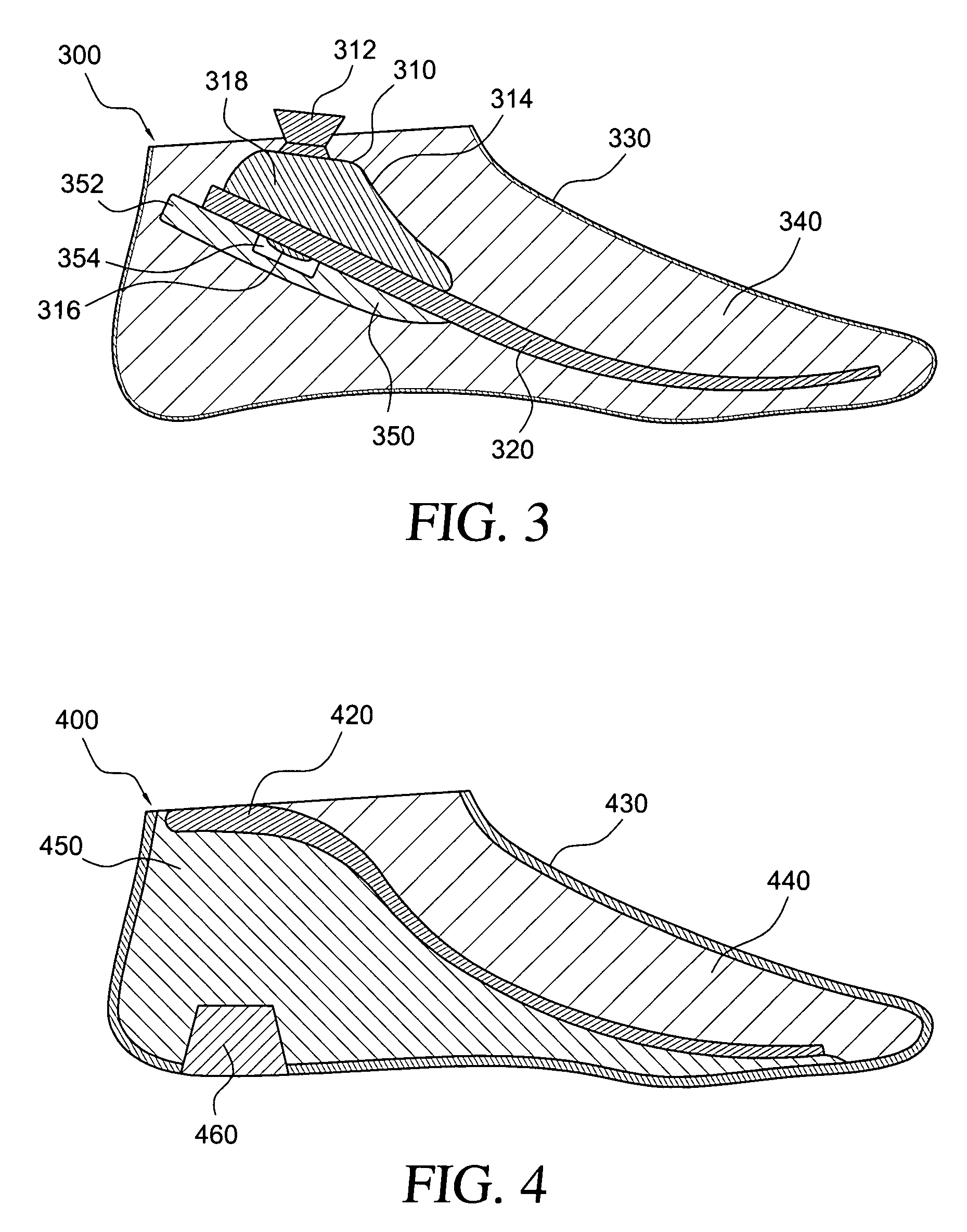
[0074]A fourth embodiment of a prosthetic foot 400 is shown in FIG. 4. A footplate 420, of any type previously discussed herein, is provided embedded between a first foam element 440 and a second foam element 450. The first and second foam elements 440, 450 may be made from materials previously discussed and may have the same density and stiffness. For example, the first and second foam elements 440, 450 may be made from an ethylene vinyl acetate (EVA) closed or open cell foam having a stiffness, as measured by the hardness, in the range of 45 to 55 on the Shore A scale.

[0075]Alternatively, the second foam element 450 may have a higher density, and thus a higher stiffness than the density of the first foam element 440. Both the first and second foam elements 440, 450 may be separately molded by known techniques and bonded to the footplate 420. Of course, the first and second foam elements 440, 450 may also be simultaneously molded integr...


PUM


Abstract

Embodiments of low cost prosthetic feet include a footplate with a connection mechanism embedded within a first foam element having a first stiffness. A second foam element is bonded to the footplate and has a recess in a proximal surface and a stiffness greater than the first foam element. The second foam element may have a portion extending past the terminal end of the footplate. A cosmesis encloses the components of the prosthetic foot. A third foam element that extends through the cosmesis into the second foam element may be provided. The third foam element may have a higher stiffness than the first and second foam elements.

Description

[0001]This application claims the benefit of U.S. Provisional Application No. 60 / 861,716, filed Nov. 30, 2006, and U.S. Provisional Application No. 60 / 817,700, filed Jul. 3, 2006.FIELD OF THE INVENTION[0002]The present invention relates generally to the field of prosthetic devices, and more particularly to prosthetic feet and footplates for use in therein.BACKGROUND[0003]In the field of prosthetics, many significant advances in construction and design of prosthetic limbs have been made possible due to improved materials and manufacturing capability. In particular, prosthetic feet and footplates for use therein have undergone large improvements in both design and construction.[0004]The use of lightweight plastics and composite materials in prosthetic feet and footplates represents a significant improvement over the previous designs, which typically included solid blocks of wood that were cosmetically shaped. In addition, the study of biomechanics and the gait cycle have allowed for i...

Claims


Application Information

Patent Timeline
Patent Type & Authority Patents(United States)
IPC IPC(8): A61F2/66
CPCA61F2/66A61F2002/30011A61F2002/30014A61F2002/30359A61F2002/30434A61F2002/5001A61F2002/5003A61F2002/5055A61F2002/6671A61F2002/6685A61F2220/0033A61F2220/0041A61F2250/0018A61F2250/0023A61F2002/30433
Inventor ASGEIRSSON, SIGURDUROLAFSSON, GUDLAUGURINGIMARSSON, GUDNI
Owner KAUPTHING BANK
Why Eureka
Try Eureka