Battery module and combination battery

a battery module and combination technology, applied in the direction of batteries, cell components, sustainable manufacturing/processing, etc., can solve the problems of obstructing the downsizing of a power source, the difficulty of obtaining an excellent handling in the case of adopting laminate-sheathed cells, etc., to achieve the effect of reducing the power source and enhancing production efficiency

Inactive Publication Date: 2009-03-17
NISSAN MOTOR CO LTD
View PDF6 Cites 14 Cited by
  • Summary
  • Abstract
  • Description
  • Claims
  • Application Information

AI Technical Summary

Benefits of technology

[0005]However, it is difficult to obtain an excellent handling in case of adopting the laminate-sheathed cells as a secondary battery, since a sufficient rigidity is not obtained between neighboring laminate-sheathed cells, or between laminate-sheathed cells mutually adhered in a stacked manner. It is therefore demanded to facilitate the handling upon assembling a plurality of unit cells, from a standpoint to increase a production efficiency.
[0007]The present invention has been carried out to satisfy the above described demand, and it is therefore an object of the present invention to provide a battery module and a combination battery, by which the handling of unit cells is facilitated to thereby enhance the production efficiency while contributing to a downsized power source.

Problems solved by technology

However, it is difficult to obtain an excellent handling in case of adopting the laminate-sheathed cells as a secondary battery, since a sufficient rigidity is not obtained between neighboring laminate-sheathed cells, or between laminate-sheathed cells mutually adhered in a stacked manner.
Further, while it is required to draw around voltage-measurement cables in order to measure voltages of the individual laminate-sheathed cells, the operation for drawing around the cables is troublesome and additional spaces are required to accommodate the cables therein, to thereby resultingly obstruct downsizing of a power source.

Method used


Image

  • Battery module and combination battery
  • Battery module and combination battery
  • Battery module and combination battery

Examples


first embodiment

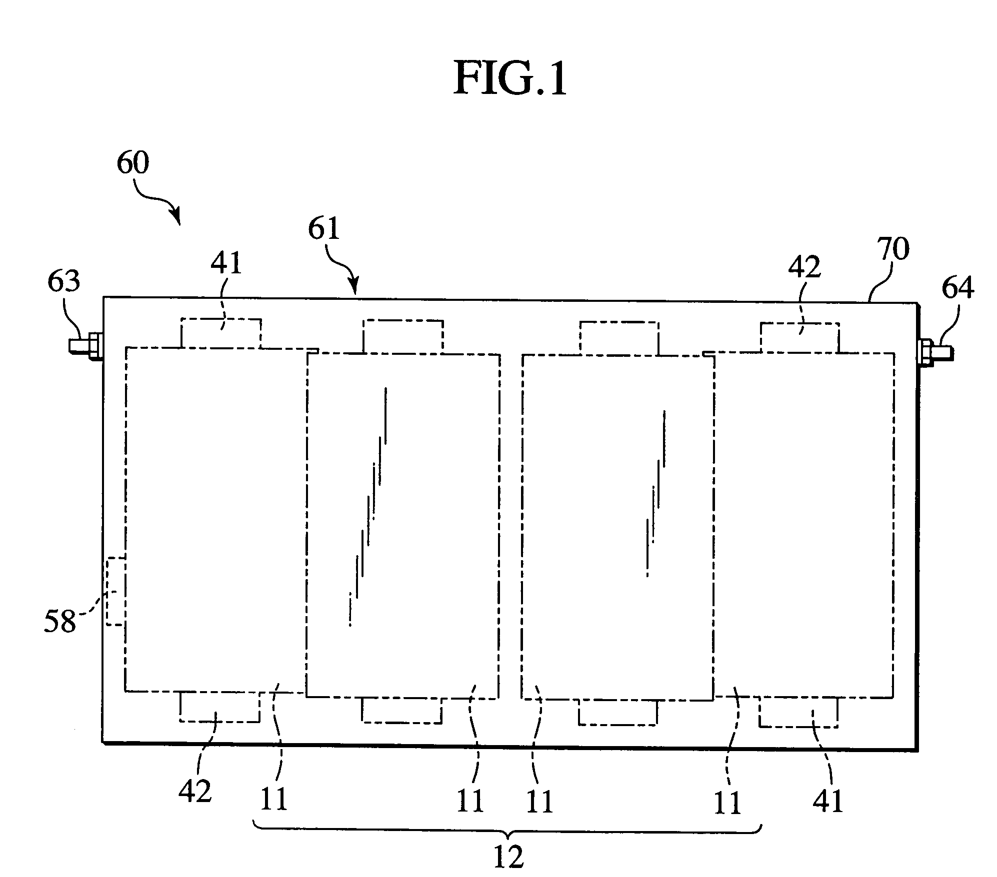
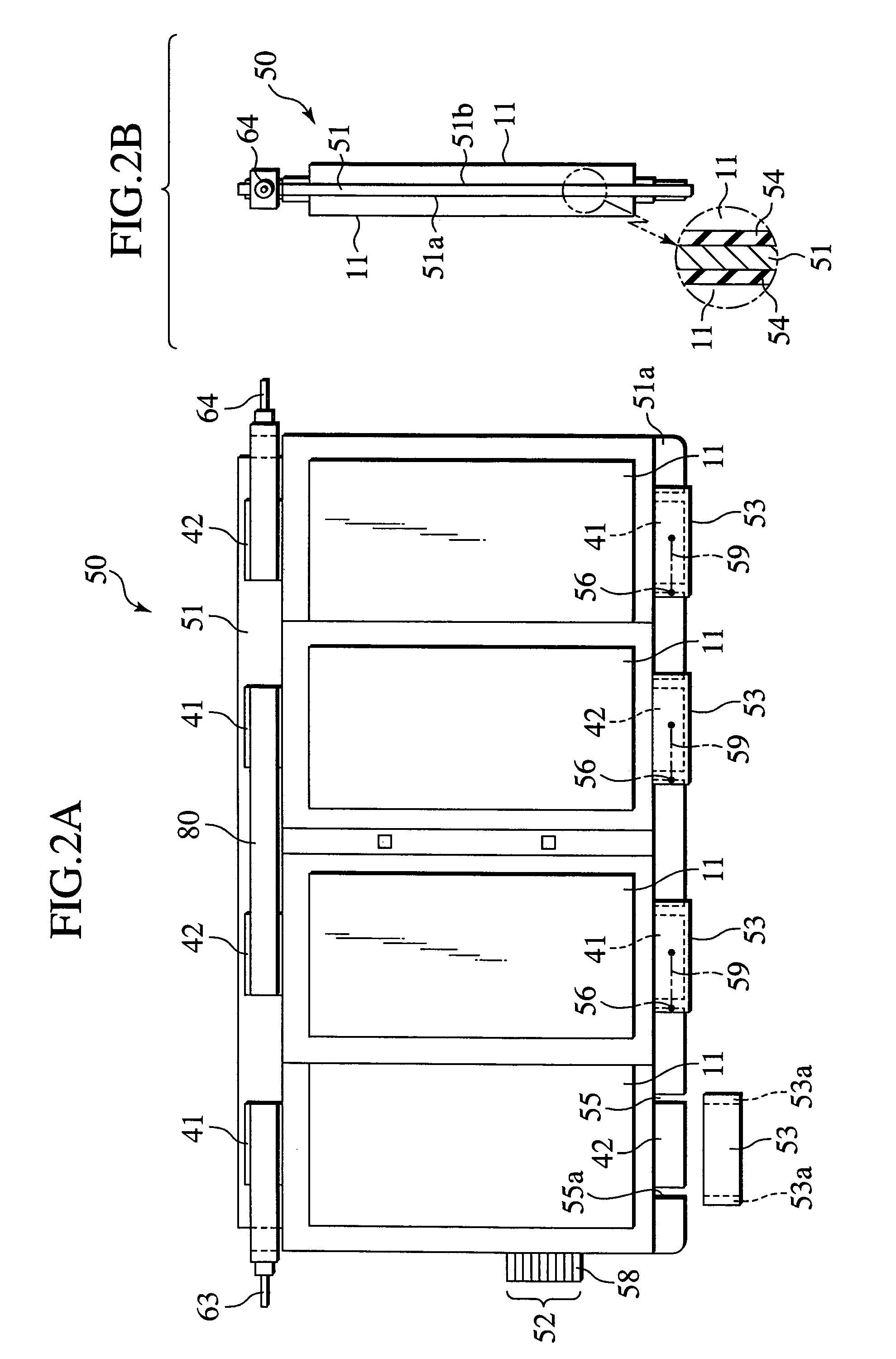
[0025]FIG. 1 is a front view of a battery module 60 according to a first embodiment of the present invention. FIGS. 2A and 2B and FIGS. 3A and 3B are a front view, side view, top view, and bottom view, respectively, of a retention member 50 in a state that the retention member 50 retains laminate-sheathed cells 11 therein, and FIG. 4 is a front view of a printed-wiring board 51 constituting the retention member 50. FIG. 5 is a perspective view of an example of the laminate-sheathed cell 11, FIG. 6A is a plan view of the laminate-sheathed cell 11, and FIG. 6B is a cross-sectional view taken along a line 6B-6B of FIG. 6A. FIG. 7A through FIG. 7C are a front view, a top view, and a side view, respectively, of a battery accommodation case 61 shown in FIG. 1.

[0026]Generally referring to FIG. 1 through FIG. 4, the battery module 60 includes: unit cells 11; the retention member 50 for retaining the unit cells 11 therein; and the battery accommodation case 61 for accommodating therein the r...

second embodiment

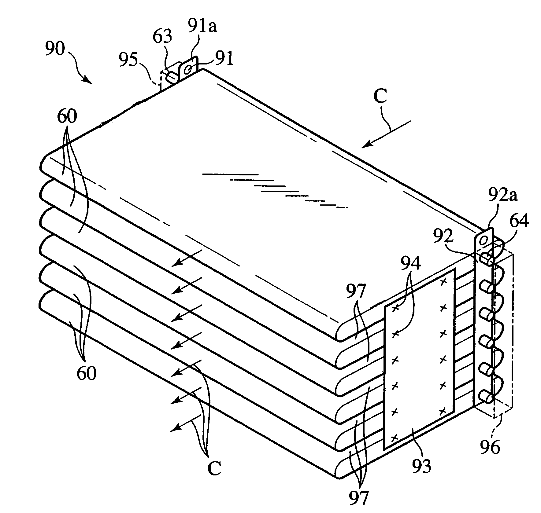
[0060]FIG. 8 is a perspective view of a combination battery 90 according to a second embodiment of the present invention, and FIG. 9 is a schematic view of a vehicle 100 comprising the combination battery 90 mounted thereon.

[0061]The combination battery 90 of the second embodiment is configured by stacking a plurality of battery modules 60 according to the first embodiment, via clearances 97 for flowing cooling air C therethrough. While the dimension of each clearance 97 may be appropriately set, there can be exemplarily adopted a dimension within a range of 2 mm to 4 mm from a standpoint for stacking the battery modules in as many stages as possible within a limited space and for realizing a preferable flow of cooling air C.

[0062]While the plurality of battery modules 60 in a combination battery may be independently used without a mutual electrical connection, the illustrated embodiment includes the combination battery 90 configured by electrically connecting the plurality of batte...

third embodiment

[0071]FIG. 10 is a front view of a printed-wiring board constituting a retention member according to a third embodiment of the present invention.

[0072]The third embodiment is provided by adding temperature detectors 110 (generic term for 110a through 110d), and temperature measurement wirings 111 (generic term for 111a through 111d) and 112 (generic term for 112a through 112d) to the printed-wiring board of the first embodiment, and constituent elements identical with those of the first embodiment are denoted by the same reference numerals and the explanation thereof shall be omitted.

[0073]Note that it is possible to control input and output voltages of the laminate-sheathed cells 11 in the secondary battery of the present invention correspondingly to the temperature characteristics of the laminate-sheathed cells 11, by individually measuring voltages of the laminate-sheathed cells 11 and individually detecting the temperatures thereof.

[0074]Arranged on the printed-wiring board 51 a...


PUM

PropertyMeasurementUnit
pressureaaaaaaaaaa
voltagesaaaaaaaaaa
voltageaaaaaaaaaa

Abstract

To provide a battery module and a combination battery, whereby the handling of unit cells is facilitated to thereby enhance the production efficiency while contributing to a downsized power source, the battery module (60) includes laminate-sheathed cells (11) as unit cells, and a retention member (50) for retaining the laminate-sheathed cells, and the retention member is configured with a printed-wiring board (51) printed with voltage measurement wirings (52) for measuring voltages of the laminate-sheathed cells, respectively.

Description

BACKGROUND OF THE INVENTION[0001]The present invention relates to a battery module and a combination battery.[0002]Recently, attention has been directed to a cell sheathed in a laminate film from a standpoint of reduced weight and the like, i.e., directed to a laminate-sheathed cell, as a secondary battery for a power source in an electric vehicle (EV) using electricity as its power source, a hybrid electric vehicle (HEV) combiningly using an engine and a motor as its power source, or the like.[0003]The laminate-sheathed cell typically comprises a laminate film having flexibility, and an electric-power generating element encapsulated within the laminate film by heat-welding an outer periphery of the laminate film. The electric-power generating element is connected with one end of an electrode lead having its other end protruded outwardly of the laminate film (see JP-A-2001-345081).[0004]In applying a secondary battery to a power source of an EV, HEV and the like, it is required to e...

Claims


Application Information

Patent Timeline
Patent Type & Authority Patents(United States)
IPC IPC(8): H01M2/24H01M50/529H01M4/42H01M6/42H01M10/00H01M10/04H01M10/48H01M50/211H01M50/224H01M50/271
CPCH01M2/348H01M10/0418H01M10/48H01M4/42H01M10/482H01M10/486H01M10/625H01M10/613H01M10/6563H01M2220/20Y02E60/10Y02P70/50H01M50/271H01M50/211H01M50/224H01M50/581
Inventor SHIMAMURA, OSAMUHORIE, HIDEAKISUZUKI, MASAAKI
Owner NISSAN MOTOR CO LTD
Why Eureka
Try Eureka