Optical apparatus having a compound tri-state non-reciprocal rotator

a tri-state non-reciprocal, optical apparatus technology, applied in non-linear optics, instruments, optics, etc., can solve the problems of limiting the total number of usable wavelengths, system using expensive wdm transmitters and/or tunable lasers, and certain limits to the scalability of these schemes, etc., to achieve easy separation, low overall cost, and easy to split

Inactive Publication Date: 2009-03-17
AGILTRON
View PDF6 Cites 17 Cited by
  • Summary
  • Abstract
  • Description
  • Claims
  • Application Information

AI Technical Summary

Benefits of technology

[0010]In view of the above prior art limitations, it is an object of the invention to provide an optical device that can employ cost-effective parts such as non-reciprocal rotators for switching a light beam to different output ports and also switching the light beam to two or more output ports simultaneously for multicasting functions.
[0011]It is a further object of the invention to provide a non-mechanical optical switching device and method compatible with optical fibers for performing routing functions including multicasting based on a few parts and at low overall cost.
[0012]These and other objects and advantages of the invention will become apparent from the ensuing description.
[0013]The objects and advantages of the invention are secured by an optical apparatus that has no moving parts and operates on a polarization state of a light beam with a compound tri-state non-reciprocal rotator. Specifically, the compound tri-state non-reciprocal rotator has a first Faraday rotator for rotating the polarization state into one of two partially rotated states at angles +α, −α, wherein α=22.5°, and a second Faraday rotator that is in communication with the first Faraday rotator and operates in conjunction therewith. The second Faraday rotator rotates the polarization state from one of the partially rotated states into one of three fully rotated states at angles +2α, 0, −2α. A polarization selection mechanism guides light in the three fully rotated states differently. More precisely, polarization selection mechanism generates a tri-state output in the form of two distinct output beams corresponding to two of the three fully rotated states, and an overlapping pair of output beams corresponding to the third of the three fully rotated states.
[0014]The two distinct output beams are in fully rotated states at angles +2α, −2α with an angular separation of 4α between them. 4α is equal to 90° and renders these fully rotated states orthogonal to each other; hence easy to separate with conventional optical elements. In contrast, the overlapping pair of output beams corresponds to fully rotated state at angle 0, which is separated from fully rotated states by an angular separation of only 2α. 2α is equal to 45° and renders polarization in fully rotated state at angle 0 easy to split with conventional optical elements to generate the overlapping pair of output beams.
[0015]The geometric configuration of the optical apparatus can vary in many ways and the three fully rotated states can be selected among different sets of final polarization states. For example, in a first set of final polarizations angles +2α, 0, −2α of the fully rotated states correspond to final polarization states of +45′, 0°, −45°. For a second set the angles +2α, 0, −2α correspond to final polarization states 0°, −45°, −90°. Of course, these final polarization states can all be rotated by increments of 90° or as convenient for any particular application.

Problems solved by technology

This means that the system has to use expensive WDM transmitters and / or tunable lasers and / or tunable filters as well as an optical amplifier.
Meanwhile, there is usually a limit to the total number of usable wavelengths imposed either by total signal power or dispersion encountered in the nonlinear medium.
Therefore, there are certain limits to the scalability of these schemes and the high power requirement may be another drawback in nonlinear optical schemes.
Although these mechanisms can be modified for multicasting, the required alterations increase the number of moving positions in mechanical switches, and require more precise control electronics in all types of switches, consequently leading to drawbacks in speed and reliability.
In addition, the complexity of the optical and electronic configuration and high losses will impose additional amplification requirements.
In addition, the fabrication costs for such a device are high.

Method used


Image

  • Optical apparatus having a compound tri-state non-reciprocal rotator
  • Optical apparatus having a compound tri-state non-reciprocal rotator
  • Optical apparatus having a compound tri-state non-reciprocal rotator

Examples


Embodiment Construction

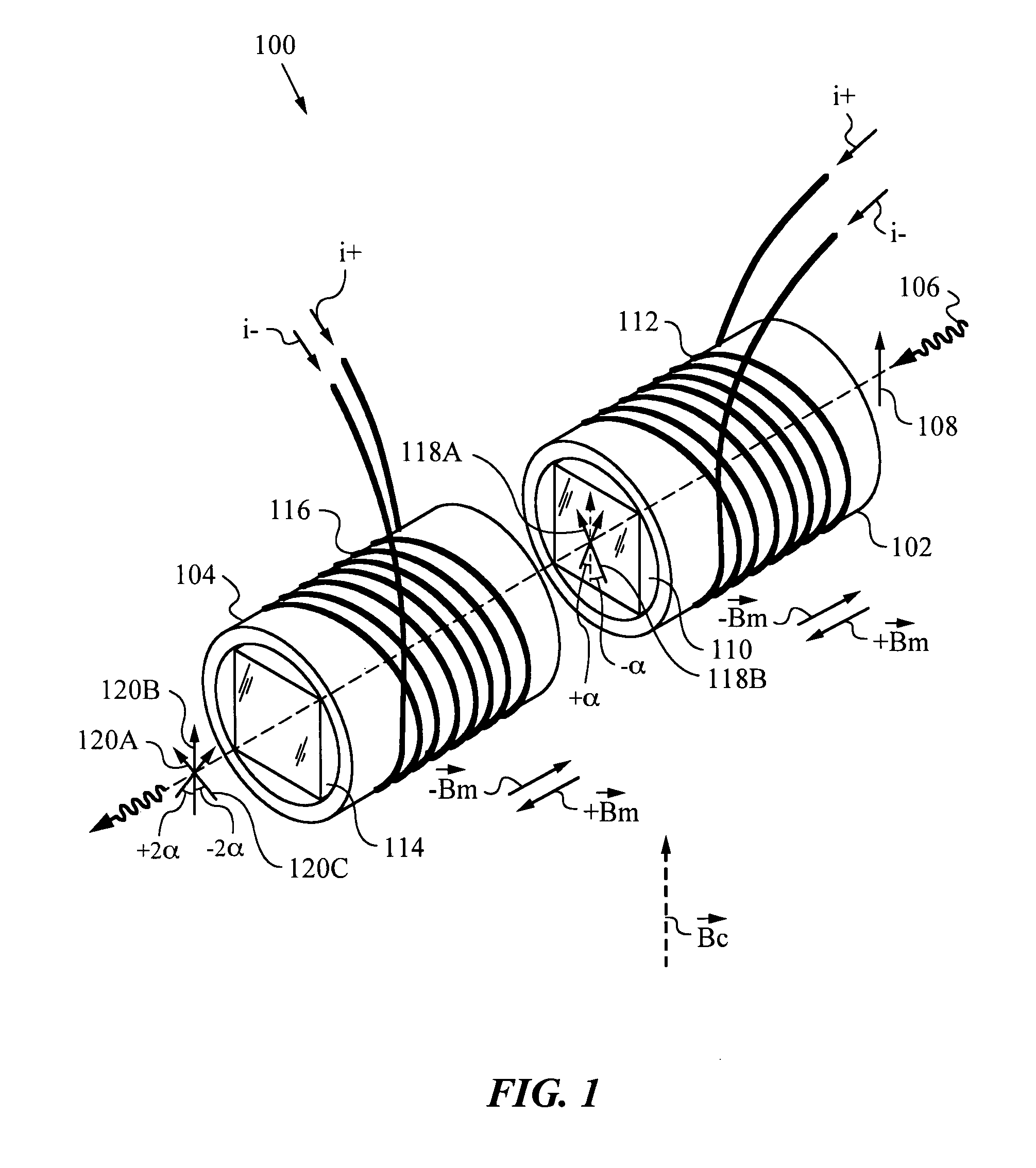
[0025]Optical devices of the invention employ a compound tri-state non-reciprocal rotator 100 as shown in FIG. 1. Tri-state non-reciprocal rotator 100 is compound because it has two Faraday rotators; namely a first Faraday rotator 102 and a second Faraday rotator 104. Faraday rotators 102, 104 are in communication with each other and are arranged in series such that a light beam 106 passes through them in succession. Light beam 106 is in a linear polarization state indicated by arrow 108.

[0026]First Faraday rotator 102 has a core 110 and a field coil 112 surrounding core 110. Field coil 112 is designed for receiving a current i and applying a modulating magnetic field Bm parallel to the direction of propagation of beam 106. More precisely, a forward current i+passing through field coil 112 generates a modulating magnetic field +Bm parallel and along the direction of propagation of beam 106. A reverse current i− generates a modulating magnetic field −Bm parallel but directed against ...


PUM

PropertyMeasurementUnit
anglesaaaaaaaaaa
anglesaaaaaaaaaa
angleaaaaaaaaaa

Abstract

An optical apparatus and methods for operating on a polarization state of a light beam using a compound tri-state non-reciprocal rotator having two Faraday rotators. A first Faraday rotator rotates the polarization state into one of two partially rotated states at angles +α, −α, where α=22.5°, and the second Faraday rotates the polarization state from one of the partially rotated states into one of three fully rotated states at angles +2α, 0, −2α. A polarization selection mechanism guides light in the three fully rotated states differently to enable various devices and different modes of operation. For example, the polarization selection mechanism can generate a tri-state output in the form of two distinct output beams corresponding to two of the three fully rotated states, and an overlapping pair of output beams obtained when the compound tri-state non-reciprocal rotator produces the third of the three fully rotated states. The various methods permitted by the invention permit simple and cost-effective multicasting switches and methods.

Description

RELATED APPLICATIONS[0001]This patent application claims priority from Provisional Patent Application No. 60 / 810,663 filed on Jun. 5, 2006 and incorporated herein in its entirety.FIELD OF THE INVENTION[0002]This invention relates generally to compound tri-state non-reciprocal rotators such as Faraday rotators in optical devices such as switches for various optical routing functions including multicasting.BACKGROUND ART[0003]Optical switches are devices that route optical signals along selected fibers of an optical network. Such switches constitute the fundamental building blocks of modern optical networks. Optical switch performance is judged by switching speed, optical insertion loss, operation lifetime, size and cost. Prior art optical switches typically operate on mechanical and opto-electronic principles. Many opto-electronic switches use birefringent elements and various types of reciprocal and non-reciprocal polarization rotators to accomplish their switching functions.[0004]R...

Claims


Application Information

Patent Timeline
Patent Type & Authority Patents(United States)
IPC IPC(8): G02F1/09
CPCG02F1/093
Inventor ZHAO, JINGJIN, GUANGHAISHU, YONGJUN
Owner AGILTRON
Why Eureka
Try Eureka