Vehicle suspension control arm and method

a technology for suspension control and control arms, applied in the direction of mechanical control devices, process and machine control, instruments, etc., can solve the problems of relatively high manufacturing costs, and achieve the effect of high strength, significant cost savings, and high strength

Inactive Publication Date: 2009-03-24
BENTELER AUTOMOTIVE CORP
View PDF35 Cites 29 Cited by
  • Summary
  • Abstract
  • Description
  • Claims
  • Application Information

AI Technical Summary

Benefits of technology

[0010]The present invention provides a light weight solution in the form of ultra high strength suspension links or control arms. The control arms may be made by using two side-by-side arm plates stamped from high strength steel. Significant costs savings during production of the control arms can be realized compared to production of aluminum and other light weight material control arms. Additionally, the materials and processes used to make the control arm provide ultra high strength without brittleness.

Problems solved by technology

Vertical loads act downwardly on the vehicle and are frequently encountered when the vehicle travels, particularly over bumps or holes in the road, inclines, etc.
While such suspension components may be made from aluminum, the same are relatively expensive to manufacture, particularly for applications requiring high structural strength and reliability.

Method used


Image

  • Vehicle suspension control arm and method
  • Vehicle suspension control arm and method
  • Vehicle suspension control arm and method

Examples


Embodiment Construction

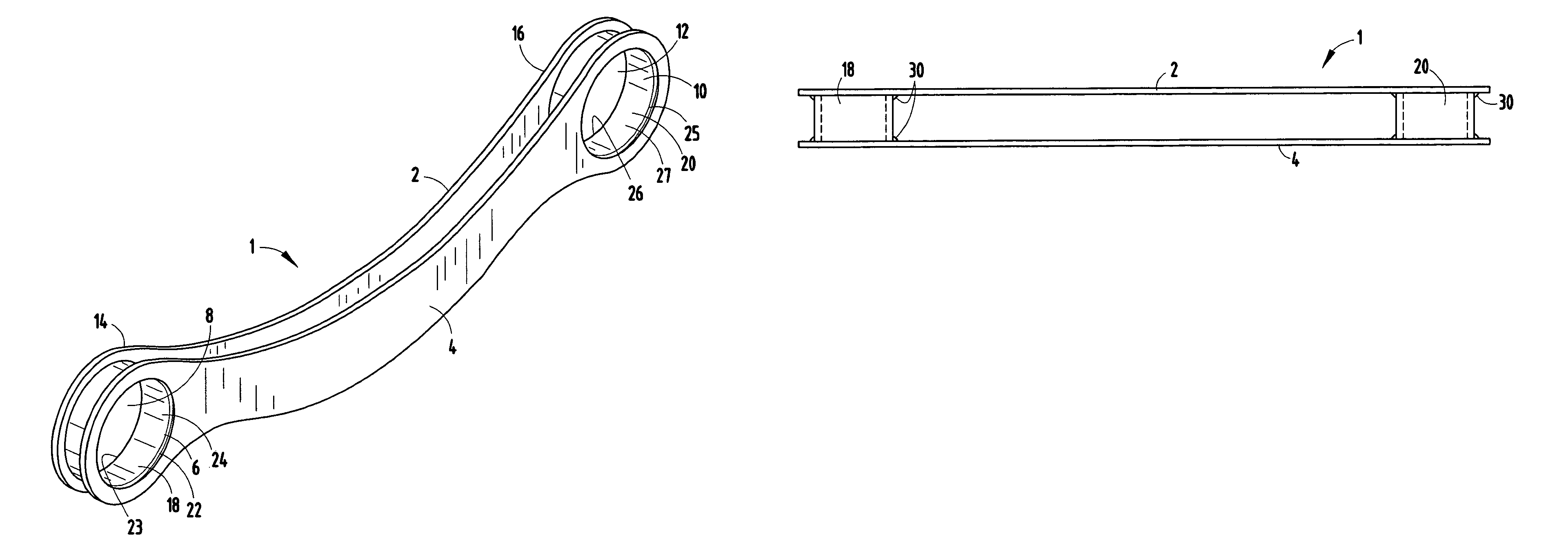
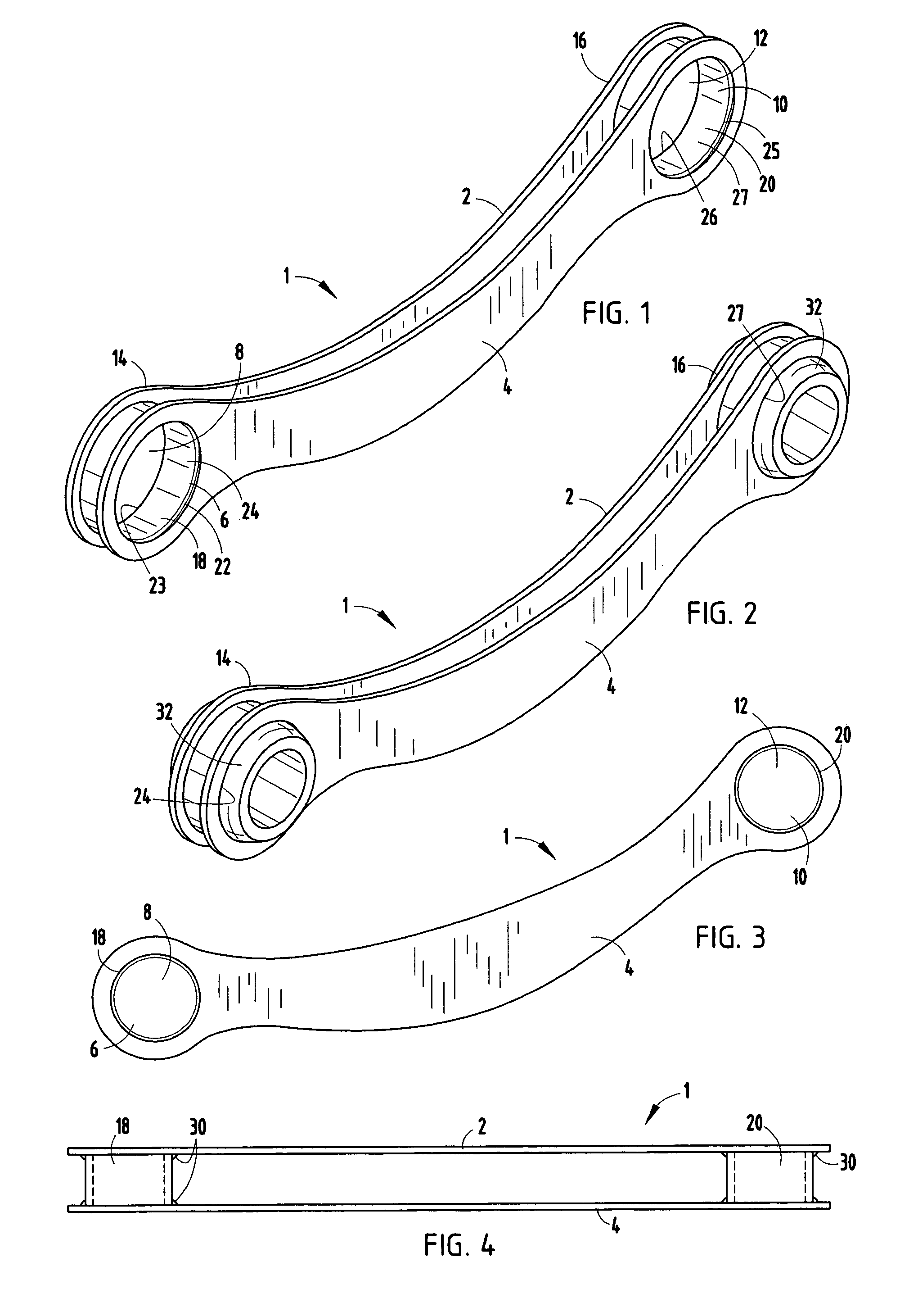
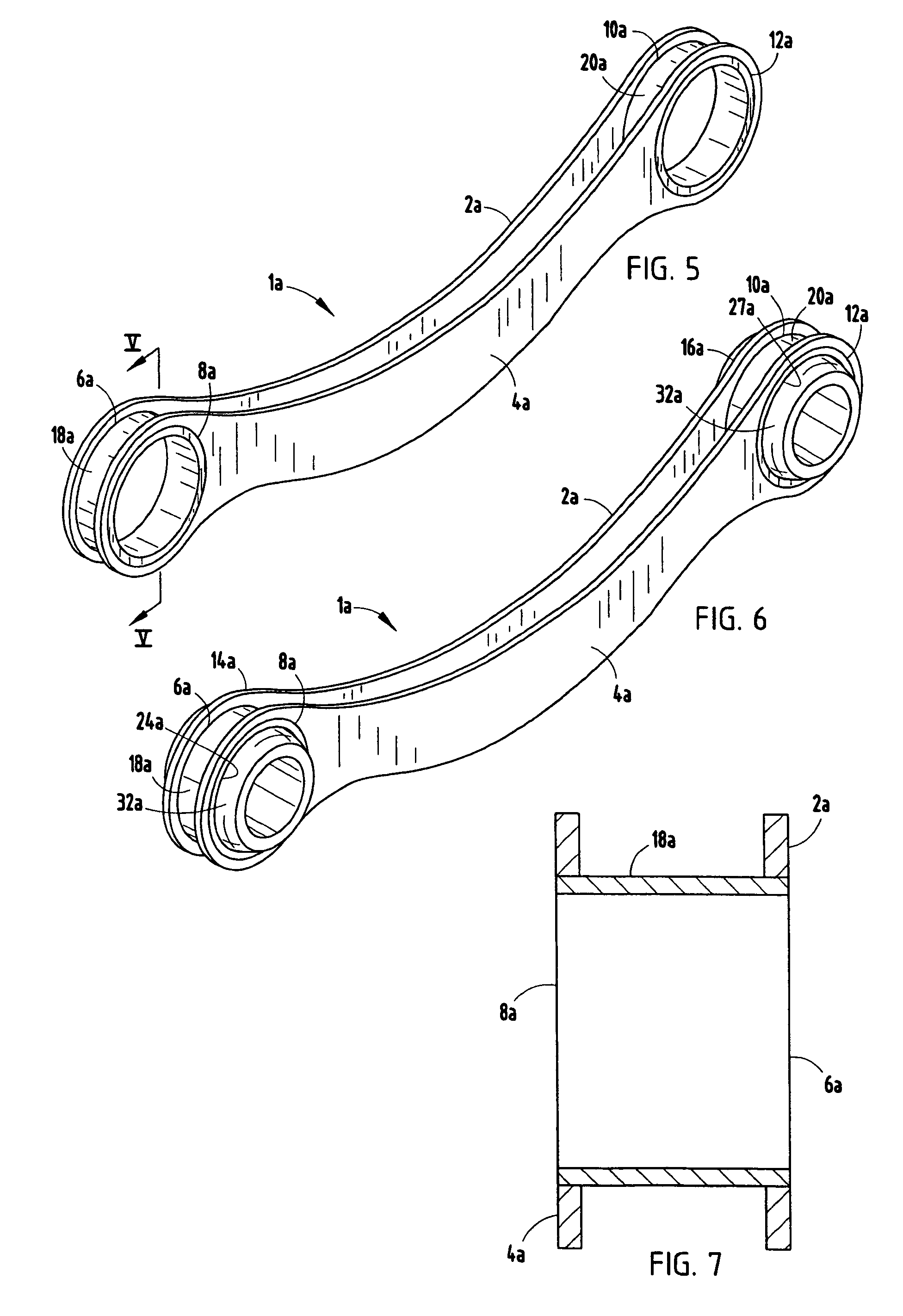
[0023]For purposes of description herein the terms “upper”, “lower”, “right”, “left”, “rear”, “front”, “vertical”, “horizontal” and derivatives thereof shall relate to the invention as oriented in FIGS. 1 and 2. However, it is to be understood that the invention may assume various alternative orientations and step sequences, except where expressly specified to the contrary. It is also to be understood that the specific devices and processes illustrated in the attached drawings, and described in the following specification are simply exemplary embodiments of the inventive concepts defined in the appended claims. Hence, specific dimensions and other physical characteristics relating to the embodiments disclosed herein are not to be considered as limiting, unless the claims expressly state otherwise.

[0024]As illustrated in FIG. 1, the reference numeral 1 generally designates a suspension link or control arm embodying the present invention, which is designed for use in a vehicle suspens...


PUM

PropertyMeasurementUnit
thicknessaaaaaaaaaa
thicknessaaaaaaaaaa
strengthaaaaaaaaaa

Abstract

A control arm for vehicle suspension systems has first and second rigid arm plates having first and second apertures extend laterally through opposing faces of the body adjacent opposite ends thereof. The arm plates are disposed in a mutually parallel, laterally spaced apart and aligned relationship. The first apertures are generally concentric and the second apertures are generally concentric. First and second spacers each have a rigid body with opposite ends and a central bushing aperture extending therebetween. The spacers are disposed between the arm plates adjacent opposite ends thereof. The central bushing aperture of the spacers is positioned generally concentrically with the apertures. Also included is a related method for making vehicle suspension links from ultra high strength steel.

Description

BACKGROUND OF THE INVENTION[0001]The present invention relates to motor vehicles and the like and in particular to a high strength vehicle suspension link or control arm and related method.[0002]During movement or operation, a variety of forces act upon the wheels of a motor vehicle. These forces are transferred from the wheels to the vehicle frame and all of its related components, and are typically referenced with respect to a vehicle in its standard horizontal position where all four wheels are in contact with the ground. Vertical loads act downwardly on the vehicle and are frequently encountered when the vehicle travels, particularly over bumps or holes in the road, inclines, etc. In addition, longitudinal forces act upon the wheels against the direction of travel while the vehicle is moving. Further, transverse forces push and pull the wheels laterally towards and away from the frame structure when the vehicle turns. A vehicle suspension system must be able to withstand the var...

Claims


Application Information

Patent Timeline
Patent Type & Authority Patents(United States)
IPC IPC(8): B21D53/88
CPCB60G7/001F16C7/08Y10T29/49995B60G2206/017B60G2206/11B60G2206/72B60G2206/722B60G2206/8102B60G2206/8103B60G2206/811B60G2206/8201B60G2206/82092B60G2206/84Y10T74/2153Y10T29/49622B60G2204/4402F16C2326/05
Inventor WEISE, KENNETH A.
Owner BENTELER AUTOMOTIVE CORP
Why Eureka
Try Eureka