
Ink jet head having an electrostatic actuator, ink cartridge, and inkjet printer

a technology of electrostatic actuator and inkjet printer, which is applied in the field of printer heads, can solve the problems of difficult control of the size of ink droplets, limited printing speed, and high price of piezoelectric type inkjet heads, and achieves the effects of reducing the composition of electrostatic type inkjet heads, increasing electrostatic force, and large displacemen

Inactive Publication Date: 2009-03-24
SAMSUNG ELECTRO MECHANICS CO LTD
View PDF11 Cites 2 Cited by
  • Summary
  • Abstract
  • Description
  • Claims
  • Application Information

AI Technical Summary

Benefits of technology

The invention is about an inkjet head with an electrostatic actuator and a manufacturing method. The invention aims to decrease the size of the inkjet head and increase the electrostatic force to achieve a larger ink discharge pressure with less voltage. The invention provides an inkjet head with a stator and rotor, joined by a diaphragm. The rotor is formed by a first component and a second component, which face each other and mesh with the stator. The invention also provides a method of manufacturing the inkjet head by joining a processed glass substrate onto a processed SOI substrate. The technical effects of the invention include decreasing the size of the inkjet head and increasing the electrostatic force, resulting in a larger ink discharge pressure with less voltage.

Problems solved by technology

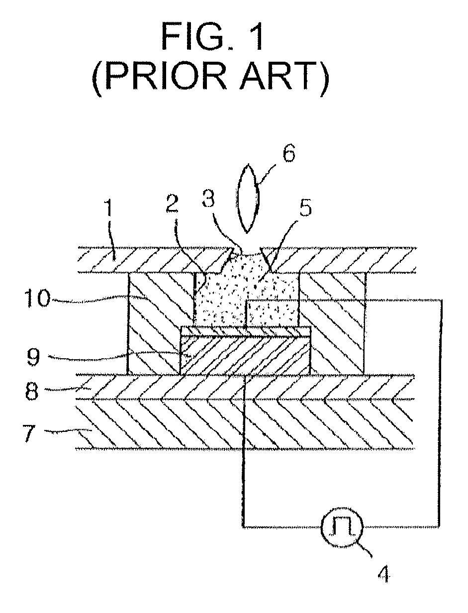
However, there are problems in durability, caused by repeated impact due to the pressure from the bubbles created by the heat; it is difficult to control the size of ink droplets; and there is a limit to increasing the printing speed.
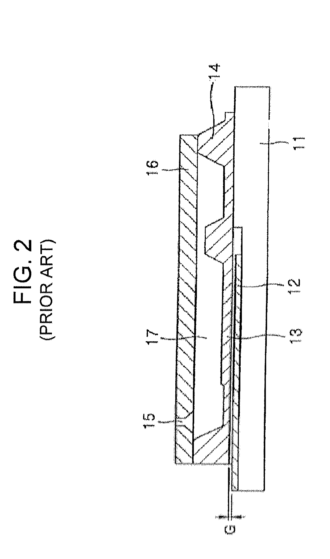
However, piezoelectric type inkjet heads are expensive, because they use costly piezoelectric elements, and the yield is low due to a complicated manufacturing process, since the piezoelectric elements must be carefully coordinated with the electrodes, insulation layer, and protection layer, etc.
This causes an increase in the occupied area per nozzle and the nozzle intervals are made wider, so that there is a limit to increasing the resolution of the printer and the manufacturing costs are increased.
Also, additional metal must be deposited to form the electrodes, which causes the manufacturing process to be more complicated.

Method used


Image

  • Ink jet head having an electrostatic actuator, ink cartridge, and inkjet printer
  • Ink jet head having an electrostatic actuator, ink cartridge, and inkjet printer
  • Ink jet head having an electrostatic actuator, ink cartridge, and inkjet printer

Examples


first embodiment

[0045]In the inkjet head having an electrostatic actuator one end of the hexagonal electrostatic actuator 100 is secured to the diaphragm 132 of the ink chamber 130, so that when voltage is supplied to the stator 110 and the rotor 120 of the electrostatic actuator 100, an electrostatic force occurs between each other, and the shape of the electrostatic actuator 100 is changed. This applies pressure on the diaphragm 132, and as the volume of the ink chamber 130 is decreased, the ink inside the ink chamber 130 is sprayed through the ink nozzle 134. When voltage is not supplied, the diaphragm 132 returns to its original position due to the recovery ability of the electrostatic actuator 100, so that the volume of the ink chamber 130 increases, and ink flows in through the ink inlet and fills the ink chamber 130.

[0046]The inkjet head having an electrostatic actuator according to the invention may operate at frequencies higher by several tens of kHz compared to the conventional thermal t...

second embodiment

[0100]Even when the first component 1221 and the second component 1241 of the rotor are separated as in FIG. 7, if an end of each component is joined to the diaphragm 132, the rotor 1201 is moved towards the stator 1101 by the electrostatic attraction, so that an end of the rotor causes the diaphragm 132 to deform, and this deformation and recovery of the diaphragm 132 allow the diaphragm 132 to apply pressure to the ink chamber 130 and discharge the ink.

third embodiment

[0101]Also, even when the stator is not a comb pattern composition with a plurality of protrusion parts in both directions as in FIG. 3, but is instead formed with a plurality of separate components 1102, 1103 as in FIG. 8, if the rotor 1222, 1242 is installed facing each stator 1102, 1103 with an end joined to the diaphragm 132, the rotors 1222, 1242 are moved towards the stators 1102, 1103 due to the electrostatic attraction between the stators and the rotors, so that as before mentioned, the ends of the rotors 1222, 1242 cause the diaphragm 132 to deform, allowing the diaphragm to pressurize the ink chamber 130.

[0102]Of course, it is preferable that the end of each of the plurality of rotors join at one position on the diaphragm, as the deformation force applied by the rotor on the diaphragm may be concentrated, a preferred embodiment of which is forming the rotor to be a hexagonal enclosure as described in FIG. 3.

[0103]FIG. 9 is a cross sectional view of an inkjet head having el...


PUM


Abstract

An inkjet head having an electrostatic actuator and a manufacturing method of the same are disclosed. The inkjet head having an electrostatic actuator, comprising a stator, on which is formed a plurality of comb pattern shaped first protrusion parts and second protrusion parts in both directions, and a rotor consisting of a first component and a second component, the ends of which join with the diaphragm, wherein a third protrusion part is formed on the first component, facing the first protrusion parts and meshing with the first protrusion parts without contact; and a fourth protrusion part is formed on the second component, facing the second protrusion parts and meshing with the second protrusion parts without contact, may decrease the size of the head composition and may increase the electrostatic force so that a large displacement may be obtained with little voltage to increase the ink discharge pressure.

Description

CROSS-REFERENCE TO RELATED APPLICATIONS[0001]This application claims the benefit of Korean Patent Application No. 2005-20531 filed with the Korea Industrial Property Office on Mar. 11, 2005, the disclosure of which is incorporated herein by reference.BACKGROUND OF THE INVENTION[0002]1. Field of the Invention[0003]The invention relates to a printer head, in particular to an inkjet head having an electrostatic actuator and a manufacturing method of the same.[0004]2. Description of the Related Art[0005]Operation types for inkjet heads include a thermal type and a piezoelectric type. For the thermal type, a heater is installed which can supply heat into the chamber by which a substantially large amount of thermal energy may be supplied in a short period of time, and bubbles are formed in the ink in the chamber so that the ink is sprayed out through nozzles. However, there are problems in durability, caused by repeated impact due to the pressure from the bubbles created by the heat; it i...

Claims


Application Information

Patent Timeline
Patent Type & Authority Patents(United States)
IPC IPC(8): B41J2/06
CPCB41J2/14314B41J2/16B41J2/1623B41J2/1628B41J2/1629B41J2/1632B41J2/164B41J2/1433
Inventor KIM, YOUNG-JAELIM, JAE-SEONGOH, SUNG-IL
Owner SAMSUNG ELECTRO MECHANICS CO LTD
Learn More