Controlled cavitation device with easy disassembly and cleaning

a cavitation device and controlled technology, applied in the direction of mixers, mixer accessories, mixing, etc., can solve the problems of time-consuming, labor-intensive, and time-consuming disassembly, and achieve the effect of high rotational speed, easy disassembly and cleaning, and high efficiency of fluid mixing

Inactive Publication Date: 2009-03-24
HYDRODYNAMICS
View PDF25 Cites 20 Cited by
  • Summary
  • Abstract
  • Description
  • Claims
  • Application Information

AI Technical Summary

Benefits of technology

[0008]Briefly described, the present invention, in one exemplary embodiment thereof, comprises a controlled cavitation device that can be disassembled, cleaned, and reassembled quickly and easily by relatively unskilled personnel. The configuration of the device is similar in many respects to the device disclosed in U.S. Pat. No. 5,957,122, which is incorporated by reference. Generally, the device includes a cylindrical rotor mounted on a shaft and disposed in a generally cylindrical housing. An electric motor or other motive means is coupled to the shaft (or the shaft can be an extension of the shaft of the motor itself). When the motor is activated, it spins the rotor at relatively high rotational speeds within its housing.
[0009]The rotor is provided on its outer periphery with a plurality of discontinuities, preferably in the form of an array of holes drilled into the rotor. Fluid to be heated or mixed is pumped through the space between the outer peripheral surface of the rotor and the cylindrical wall of the housing. As the rotor turns, violent cavitation events are induced in the fluid in the regions of the holes. The energy released by this cavitation heats the fluid and, where two fluids are introduced, has a wide variety of desirable effects including highly efficient mixing of the fluids, efficient inducement of chemical reactions within the fluids, and many others. Such effects are disclosed and discussed in detail in the patents and patent applications incorporated by reference.
[0010]In addition to the benefits of the devices and methods in the incorporated references, the present application provides structure and methodology for disassembling a controlled cavitation device easily for cleaning, and then easily reassembling the device for use. Generally, this is accomplished through a uniquely designed rotor housing assembly. The rotor housing generally is formed by a cylindrical peripheral wall that is capped on its ends by disc-shaped end plates. The end plates have a larger diameter than the wall so that a mounting flange is formed by the radially projecting edge portions of the end plates. The inboard end plate (i.e., the one closest to the motor) is mounted on and is a part of the support structure connected to the bearing housing. The rotor shaft extends through bearings in this end plate to be coupled through a bearing housing to the motor.
[0011]The outboard end plate is secured to the cylindrical wall. An array of bolts extends through the flange of the outboard end plate and is positioned therearound. The subassembly formed by the outboard end plate and the cylindrical wall is mounted to the inboard end plate to form the closed housing that encloses the rotor. Specifically, this subassembly is moved over the rotor and the bolts extending through its peripheral flange are threaded into threaded bores in the peripheral edge portion of the inner plate, thereby securely bolting the housing assembly together.
[0012]In the present invention, each bolt of the array of bolts used to secure the housing components together is provided with a hand knob on the outboard end plate in order to reduce the use of tools in the disassembly process, which is highly desired in the food processing industry. The subassembly comprising the outboard end plate and cylindrical wall of the housing is mounted on a swing arm located adjacent to the device. This allows the subassembly to be swung out of the way when disconnected so that it, and the then exposed rotor assembly, can be thoroughly cleaned. Afterwards, the swing arm allows the subassembly to be swung back into place easily and secured to the inboard end plate. Alignment pins or dowels are provided in the inside edge of the cylindrical wall and corresponding holes are provided in the inside plate. When the subassembly is properly aligned with the inside plate, the alignment pins register with the holes to position the subassembly properly before it is bolted in place. An O-ring in the edge of the cylindrical wall forms a seal against the inboard end plate to seal the interior of the housing.

Problems solved by technology

Prior art controlled cavitation devices disclosed in the incorporated references can be disassembled, but such disassembly requires laborious, tedious, and time consuming efforts and generally requires special tools and an engineer or technician that is significantly skilled in the operation and maintenance of the device.
This is not desirable for industries such as the food processing industry, which expect machines used for processing food to be able to be disassembled, cleaned, and reassembled quickly, easily, and by low-skilled food processing personnel.

Method used


Image

  • Controlled cavitation device with easy disassembly and cleaning
  • Controlled cavitation device with easy disassembly and cleaning
  • Controlled cavitation device with easy disassembly and cleaning

Examples


Embodiment Construction

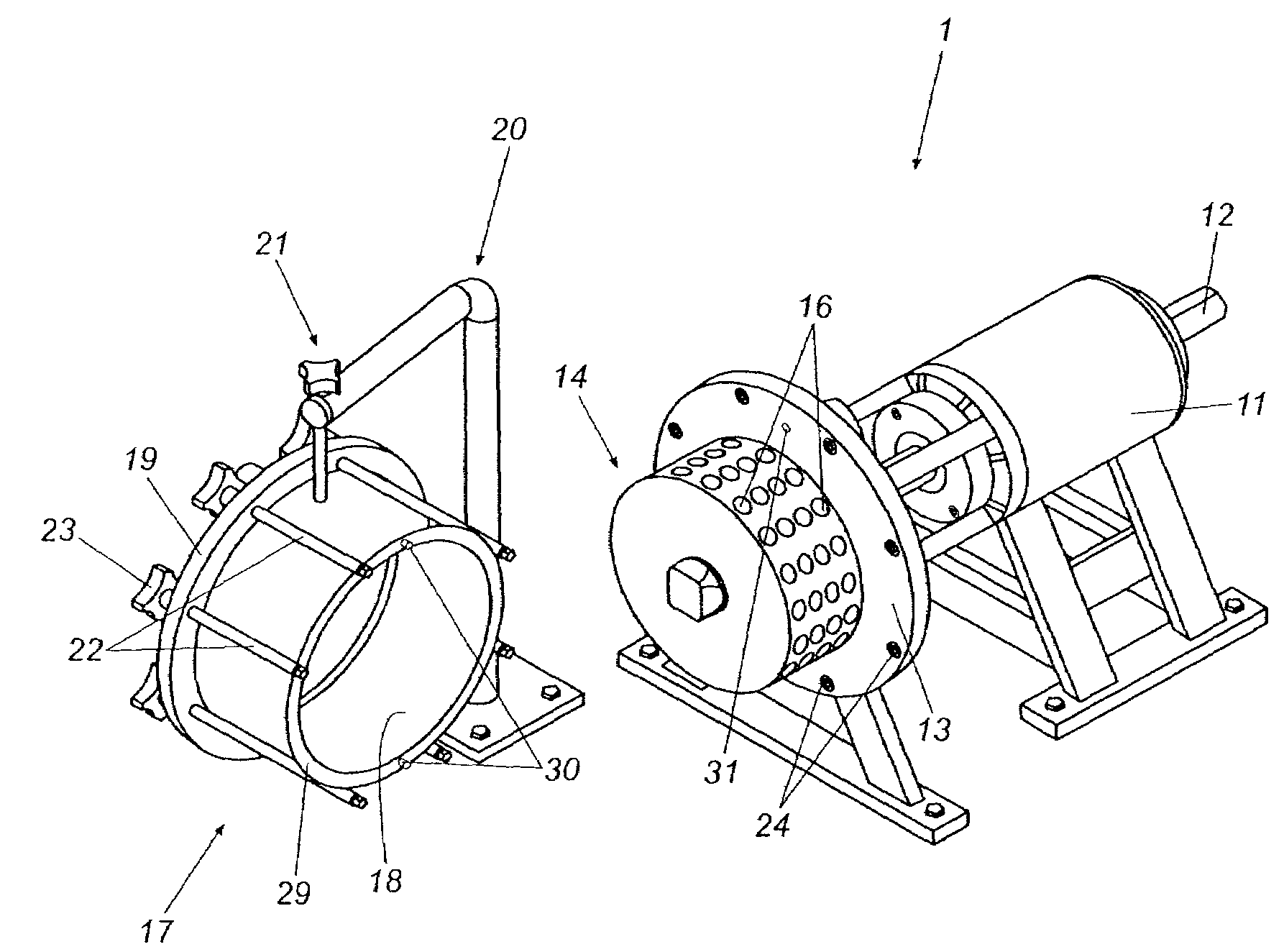
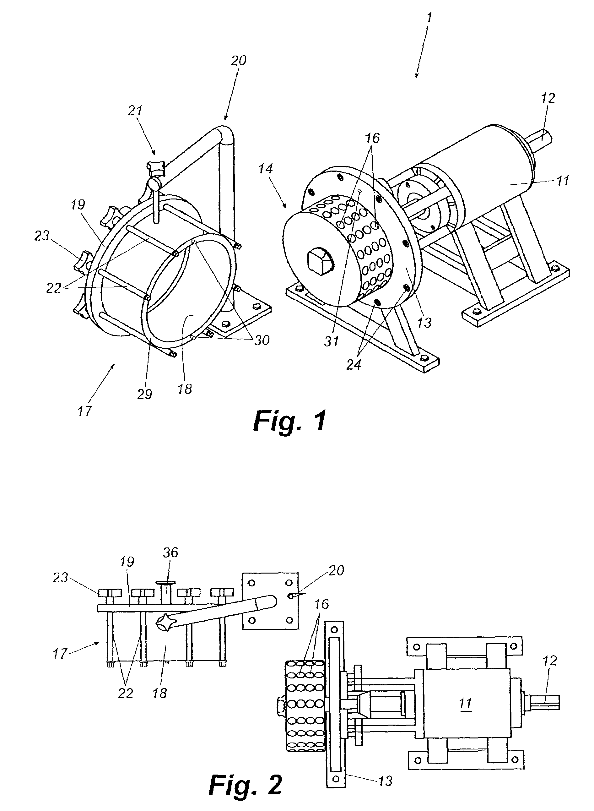
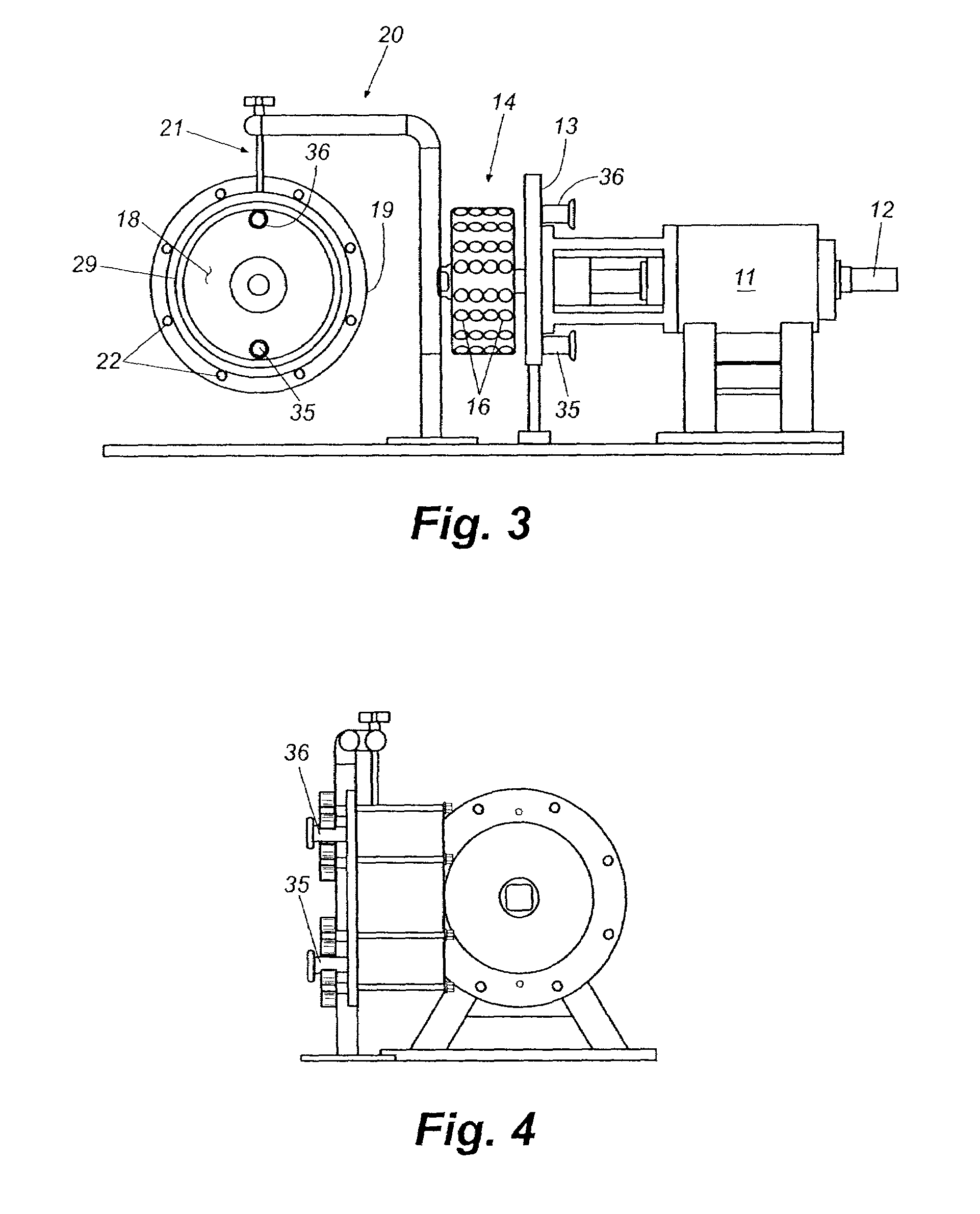
[0019]The following description of the invention is provided as an enabling teaching of the invention and its best, currently known embodiment. Those skilled in the art will recognize that many changes can be made to the embodiments described while still obtaining the beneficial results of the present invention. It will also be apparent that some of the desired benefits of the present invention can be obtained by selecting some of the features of the present invention without utilizing other features. Accordingly, those who work in the art will recognize that many modifications and adaptations of the invention are possible and may even be desirable in certain circumstances and are part of the present invention. Thus, the following description is provided as illustrative of the principles of the invention and not in limitation thereof since the scope of the present invention is defined by the claims.

[0020]Referring now in more detail to the drawing figures, wherein like reference num...


PUM


Abstract

A controlled cavitation device for mixing and heating of fluids in industries where sanitary conditions must be maintained. The device is easily disassembled for thorough cleaning and then easily assembled for continued operation. All internal surfaces are devoid of angles and are polished to food industry standards to maintain sanitary operation. The controlled cavitation device includes a cylindrical bearing housing for supporting a drive shaft that extends through each end of the bearing housing. An interior end plate is mounted to a C-face mount adjacent to the bearing housing and has a plurality of threaded bores around a periphery. A rotor is mounted adjacent to the interior end plate on the C-face mount. A housing assembly includes a cylindrical housing wall and is mounted on a swing arm assembly that is secured in place adjacent to the rotor. The housing assembly is rotated about a pivot arm in a first direction to fully enclose the rotor during assembly and is rotated in an opposite direction to expose the rotor during disassembly. An exterior end plate is fixed to one end of the housing wall to form a flange for connecting the housing assembly to the interior end plate.

Description

CROSS-REFERENCE TO RELATED APPLICATION[0001]The present patent application is a formalization of a previously filed, provisional patent application entitled “Controlled Cavitation Mixing Device with Easy Disassembly and Cleaning,” filed on Aug. 5, 2005 as U.S. patent application Ser. No. 60 / 705,752, by the inventors named in this patent application. This patent application claims the benefit of the filing date of the cited provisional patent application according to the statutes and rules governing provisional patent applications, particularly 35 USC § 119 (e)(1) and 37 CFR §§ 1.78(a)(4) and (a)(5). The specification and drawings of the provisional patent application are specifically incorporated herein by reference.FIELD OF THE INVENTION[0002]The present invention relates generally to devices for heating fluids and mixing dissimilar fluids using controlled cavitation and more specifically to such controlled cavitation devices that can be disassembled, cleaned, and reassembled easil...

Claims


Application Information

Patent Timeline
Patent Type & Authority Patents(United States)
IPC IPC(8): B01F7/02B01F7/12B01F27/74
CPCB01F7/00816B01F15/00922B01F27/2722B01F35/10
Inventor LEAGUE, RICHARD D.PARKER, DEREK E.
Owner HYDRODYNAMICS
Why Eureka
Try Eureka