High efficiency solar powered fan

Active Publication Date: 2009-03-24
UNIV OF CENT FLORIDA RES FOUND INC
View PDF41 Cites 49 Cited by
  • Summary
  • Abstract
  • Description
  • Claims
  • Application Information

AI Technical Summary

Benefits of technology

[0013]The first objective of the subject invention is to provide efficient roof/attic exhaust fans, blades, devices, apparatus and m

Problems solved by technology

This buildup of hot air can lead to poor cooling conditions within the building and increased utility costs to run air conditioning systems and cooling systems, and the like.
Existing attic ventilation fans have been used but have substantial power requirements from existing building electrical supplies.
Flat type blades are not designed to maximize moving of air.
However, none of the cited references, individually or in combination overcome all the problems with the prior art described above.
However, the air conditioner condenser fans are not optimized for the ventilation and removal of air from underneath roofs and from attic spaces.
None of these propellers are designed for optimizing airflow to remov

Method used


Image

  • High efficiency solar powered fan
  • High efficiency solar powered fan
  • High efficiency solar powered fan

Examples


embodiment 200

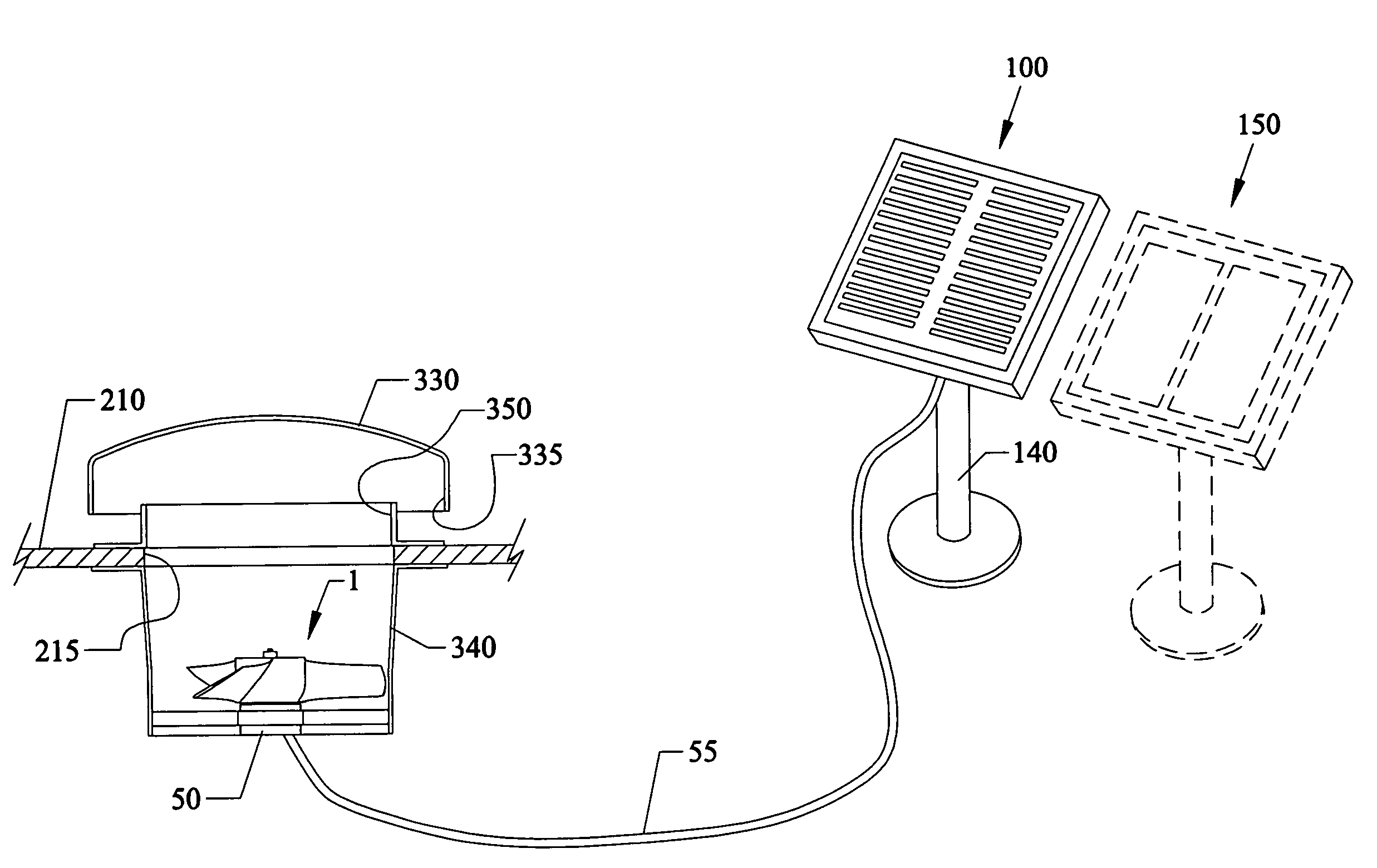
[0105]FIG. 6 is a perspective exterior view of a roof alcove exhaust embodiment 200 incorporating the fan 1 and blades 10, 20, 30 of the preceding figures with a solar power source 100. FIG. 7 is a view of the separate components of FIG. 6.

[0106]Referring to FIGS. 6-7, the novel fan 1 can be mounted with blades 10-30 facing to exhaust sideways in a housing 240 inside of an opening 225 in a gable side wall 220 below a roof 210. The outer hood 230 with covers 235 can cover the opening 225 in the gable side wall 220. The fan motor 50 can draw power through cable / power line 55 from a rooftop mounted solar power source 100, which can include two PV (photovoltaic) panels 110, 120 in a frame 130 that can be directly attached (by screws, and the like) into the roof 210. An optional stand 140 can be used to elevate the solar panels 110, 120 and frame 130 above the roof 210. Additional power can be provided by another solar power source 150.

Roof Top Exhaust

[0107]FIG. 8 is another perspective ...

embodiment 400

[0123]FIG. 10 is a perspective front view of a portable fan 400 incorporating the fan 1 and blades 10, 20, 30 of the preceding figures with a solar power source 470. FIG. 11 is a rear view of the portable fan 400 of FIG. 10. The portable fan embodiment 400 combines a high efficiency fan 1 in a cylindrical housing 410 with a portable stand that can consist of a telescopingly height adjustable pole 420 with triangular shaped base 430 having wheels 440. The triangularly shaped base 430 can have a rear generally straight edge 432 with wheels 440 mounted at each end, angled sides 434, 436 meeting at a rounded apex 438. The shape of the base 430 allows the fan 400 to be easily tilted back in the direction of arrow B so that a user can move the fan 400 with only two wheels 440 by gripping the handle 450 that is attached to the upper pole 420 of the portable fan 400.

[0124]A handtruck type stand 480 having an L-shape with wheels 485 on the lower end and hand rails 482 can support solar power...


PUM


Abstract

Highly efficient ventilation fans for exhausting air out from underneath roofs, and/or for being portable in use and application. The fan can include optimized airflow blades having a twisted configuration that can move at a rotational speed operation of up to approximately 500 rpm. The approximately 15 inch diameter twisted blades can be premolded on a hub that together form a single molded unit of plastic. They can also be fabricated using metal. The unit can be mounted in an exhaust outlet having a conical diffuser on or adjacent to a roof. Alternatively, the fan can be portable for use most anywhere there is a need for ventilation and moving of air. The blades can rotate by a solar powered motor, where the blades and motor can generate up to approximately 1040 cfm while using no more than approximately 16 Watts.

Description

FIELD OF INVENTION[0001]This invention relates to solar powered fans, and in particular to efficient attic exhaust fans and portable fans having optimized twisted nonmetal blades that are solar powered, and to methods of operating the novel fans.BACKGROUND AND PRIOR ART[0002]Ventilation fans for venting hot air from attic areas underneath roofs have been increasing in popularity over the years. Hot air is known to accumulate under roof tops especially in attic areas. This buildup of hot air can lead to poor cooling conditions within the building and increased utility costs to run air conditioning systems and cooling systems, and the like. Thus, it is desirable to improve and maximize air removal rates from under roofs and from attic spaces, and the like.[0003]Existing attic ventilation fans have been used but have substantial power requirements from existing building electrical supplies. For example, the GRAINGER® catalog sells an automatic power attic gable ventilator model number ...

Claims


Application Information

Patent Timeline
IPC IPC(8): F24F7/02F24F13/20F24F7/06
CPCF24F7/025Y10S454/90
Inventor PARKER, DANNY S.HIBBS, BART
Owner UNIV OF CENT FLORIDA RES FOUND INC
Why Eureka
Try Eureka