Electronic device

a technology of electronic devices and electromagnetic noise, applied in the field of electronic devices, can solve the problems of poor energy use efficiency and achieve the effect of suppressing electromagnetic noise and stable communication signal processing

Active Publication Date: 2009-03-24
ABLIC INC
View PDF4 Cites 31 Cited by
  • Summary
  • Abstract
  • Description
  • Claims
  • Application Information

AI Technical Summary

Benefits of technology

[0012]The present invention has been made in view of the above inconveniences of the prior art, and it is an object of the invention to reduce power consumed wastefully by interrupting a power source and an electronic circuit completely when the electronic circuit is not being operated.
[0014]Therefore, the wasteful power consumed in the electronic circuit in a standby state can be reduced, which enhances energy use efficiency of an entire system.
[0015]The electronic device of the present invention as described above includes a power generation source for generating power using environmental energy, and a charge / discharge circuit that is driven with the power of the power source to control the switch circuit. Therefore, the following effects can be obtained.
[0016](1) In a case where the power source is a battery, a life of the battery in the entire system can be prolonged.
[0018](3) Owing to a booster circuit, even when output voltage of the power generation source is small, the switch can be controlled.
[0020](5) In a case where the electronic circuit is a communication circuit, generation of electromagnetic noise can be suppressed by employing a charge pump system using the capacitor for the booster circuit. Therefore, the communication circuit can perform stable communication signal processing.

Problems solved by technology

The load circuit 107 consumes power even in a standby state where the circuit is not being operated, so energy use efficiency has been very poor.

Method used


Image

  • Electronic device
  • Electronic device
  • Electronic device

Examples


first embodiment

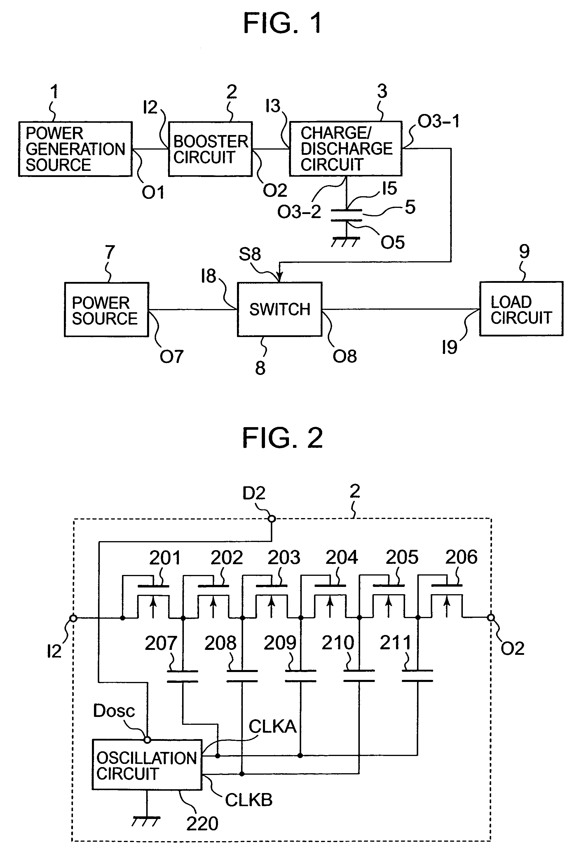
[0030]FIG. 1 is a block diagram of an electronic device according to a first embodiment. The electronic device includes a power generation source 1, a booster circuit 2 for boosting power generation voltage of the power generation source 1, a capacitor 5 for storing boosting power boosted by the booster circuit 2, a charge / discharge circuit 3 for monitoring the stored voltage in the capacitor 5 to control charge / discharge of the capacitor 5, and turning on / off the switch circuit 8, a power source 7, a switch 8, and a load circuit 9 that is driven with power of the power source 7.

[0031]As the power generation source 1, for example, a solar battery, a thermal power generator, a piezoelectric element, a power generator for converting rotation energy into electricity, a power generator for converting the change in a magnetic field and an electromagnetic field into electricity, or the like is used. These power generation sources have small power generation voltage per basic unit element,...

second embodiment

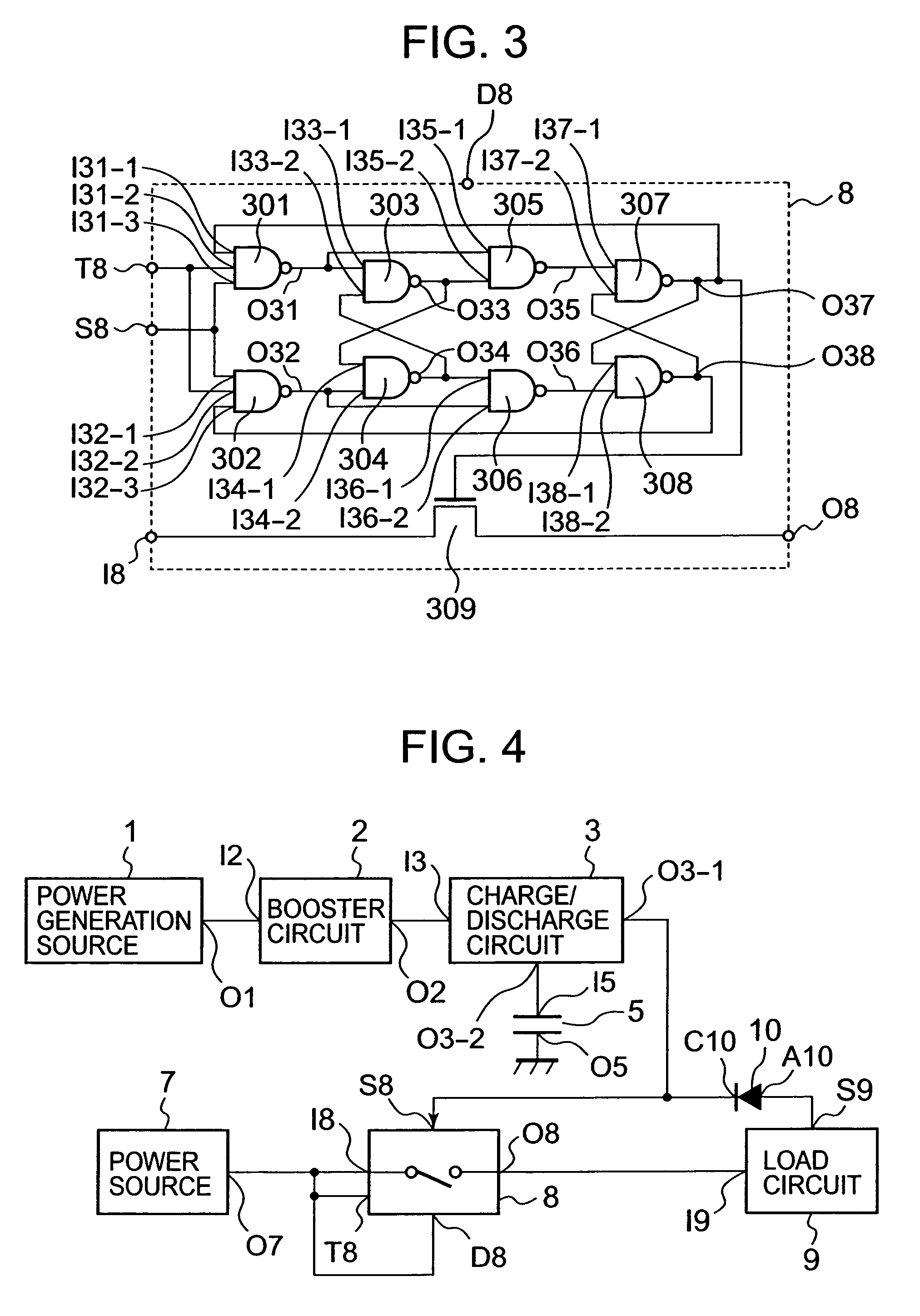
[0043]FIG. 4 is a block diagram of an electronic device according to a second embodiment. In the electronic device of the second embodiment, a switch has a configuration including a latch circuit as shown in FIG. 3. If the switch has a latch function, when power is supplied to change a state, the changed state is kept until a signal is input again. Therefore, it is desirable that the switch 8 has a latch function. An object of the electronic device of the present invention is to reduce power consumption. Therefore, an effect of the present invention is further enhanced by using a latch-type switch.

[0044]As a switch having a latch function, a mechanical switch with a latch mechanism using an MEMS technique, a switch obtained by combining a MOSFET and a flip-flop circuit, or a latch switch in which a rotation switch is connected to a stepping motor of a clock is used. Hereinafter, the configuration of a switch obtained by combining a MOSFET and a flip-flop circuit, which is an exempla...

third embodiment

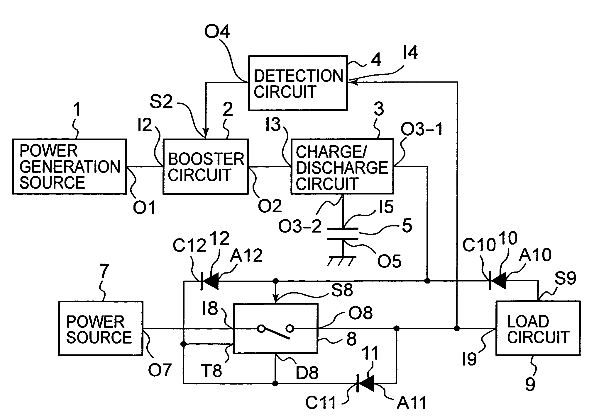
[0050]FIG. 5 is a block diagram of an electronic device of the third embodiment. In the electronic device of the third embodiment, a detection circuit 4 for monitoring the ON state of the switch 8 is provided, and has a function of forcefully stopping the operation of the booster circuit 2 when the switch 8 is in an ON state.

[0051]The electronic device of the third embodiment connects the output terminal O1 of the power generation source 1 to the input terminal I2 of the booster circuit 2, and connects the output terminal O2 of the booster circuit 2 to the input terminal I3 of the charge / discharge circuit 3. The charge / discharge terminal O3-2 of the charge / discharge circuit 3 is connected to the input terminal I5 of the capacitor 5, the ground terminal O5 of the capacitor 5 is grounded, and the output terminal O3-1 of the charge / discharge circuit 3 is connected to the control terminal S8 of the switch 8. The output terminal O7 of the power source 7 is connected to the input terminal...


PUM


Abstract

Provided is an electronic device capable of completely interrupting a power source and an electronic circuit when the electronic circuit is not being operated, and reducing power consumed wastefully. In the electronic device including the power source, a switch, and the electronic circuit, the power source and the electronic circuit are electrically interrupted by the switch when the electronic circuit is not being operated. The electronic device further includes a power generation source for converting environmental energy into electric energy, and a switch control circuit driven by the power generation source.

Description

[0001]This application claims priority under 35 U.S.C. §119 to Japanese Patent Application No. 2005-223741 filed Aug. 2, 2005, the entire content of which is hereby incorporated by reference.BACKGROUND OF THE INVENTION[0002]1. Field of the Invention[0003]The present invention relates to an electronic device, which is operated with a power source having a low output voltage and generates power using environmental energy.[0004]2. Description of the Related Art[0005]FIG. 8 shows a block diagram of a conventional electronic device. The electronic device includes a power source 101 for supplying power, a load circuit 107, a switch 103 for connecting the power source 101 and the load circuit 107, a switch control circuit 102 for controlling the switch 103, a capacitor 105 for storing power used for driving the switch control circuit 102, a charge / discharge control circuit 104 for supplying power from the power source 101 to the capacitor 105 when the power stored in the capacitor 105 beco...

Claims


Application Information

Patent Timeline
Patent Type & Authority Patents(United States)
IPC IPC(8): H03K17/16
CPCH02J7/32H02J9/005Y02B70/30Y04S20/20
Inventor YOSHIDA, YOSHIFUMI
Owner ABLIC INC
Why Eureka
Try Eureka