Hardware configuration for pressure driver

a driver and hardware technology, applied in the field of breathing apparatus, can solve the problems of affecting the overall clinical effectiveness of respiratory care, and affecting the ability of respiratory care staff to respond to the needs of infants,

Active Publication Date: 2009-03-31
VYAIRE MEDICAL 211 INC
View PDF38 Cites 156 Cited by
  • Summary
  • Abstract
  • Description
  • Claims
  • Application Information

AI Technical Summary

Benefits of technology

[0014]The mixture control may be configured to provide oxygen gas at any concentration ranging from zero percent to 100 percent as measured by an oxygen sensor that may also be incorporated into the pneumatic circuit. In CPAP treatment, the mixture control may be periodically adjusted in order to gradually reduce patient dependency upon the oxygen concentration as the patient acquires normal respiratory function.
[0016]An inspiratory check valve may be further included in the pneumatic circuit and is preferably operative to block the flow of pressurized gas in a direction toward the inspiration flow control valve. A safety valve may be also incorporated into the pneumatic circuit and may cooperate with the inspiratory check valve as a secondary safety feature for ventilating the patient in the event of a malfunction of the ventilation system. In this manner, the patient may receive adequate ventilation despite loss of gas flow from the inspiration flow control valve.

Problems solved by technology

Although the use of such breathing devices have generally proven to be suitable for their intended purposes, such devices possess certain design deficiencies which detract from their overall clinical effectiveness in providing respiratory care.
Unfortunately, variations in pressure may occur during CPAP therapy.
Such pressure variations may be the result of leakage occurring in the ventilation system.
For example, for infant ventilators using a patient interface configured with nostril-engaging stems, leaks may develop over time between the nostril-engaging stems and the infant's nose.
If the patient interface is configured as a nasal mask covering the mouth and / or nose, leaks may also occur due to improper fitment of the mask to the patient's face or due to slippage of the mask during ventilation.
Unfortunately, because of the non-adjustable nature of manual flow control valves as used in prior art infant ventilator devices, such leakage in the ventilation system may go undetected and may result in a loss in pressure at the patient.
Additionally, many infant ventilator devices of the prior art lack the capability for detecting leakage or detecting disconnections at the patient circuit.
Furthermore, infant ventilator devices of the prior art lack the means for correcting for pressure losses at the patient as a result of such leakage and / or disconnections.

Method used


Image

  • Hardware configuration for pressure driver
  • Hardware configuration for pressure driver
  • Hardware configuration for pressure driver

Examples


Embodiment Construction

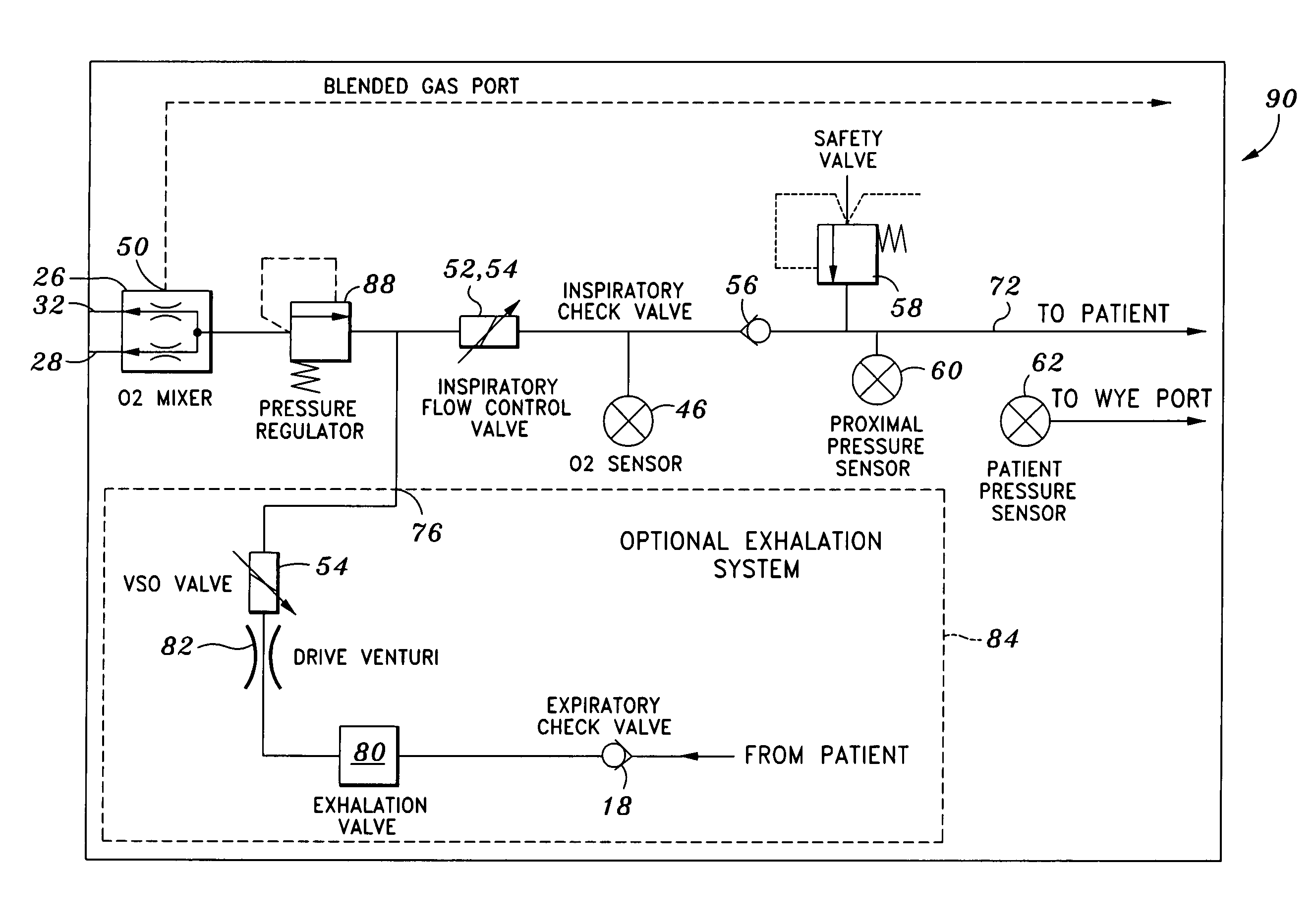
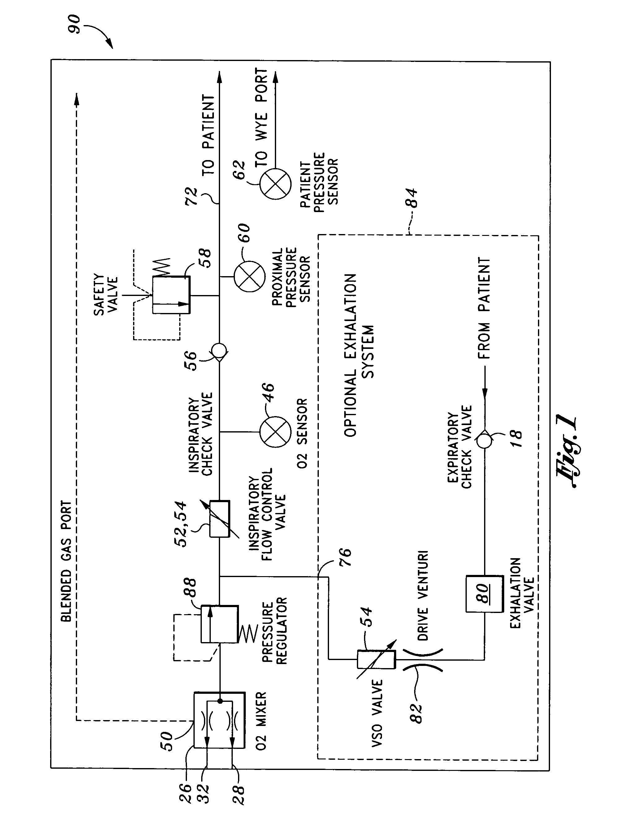
[0026]Referring now to the drawings wherein the showings are for purposes of illustrating preferred embodiments of the present invention only, and not for purposes of limiting the same, FIG. 1 is a pneumatic diagram of a ventilation system as may be used for providing continuous positive airway pressure (CPAP) therapy to a patient. The ventilation system includes a pressure driver 10 for providing pressurized gas to the patient. Although not shown in FIG. 1, the ventilation system may also include a flow generator or micro generator (not shown) patient circuit such as that which is disclosed in U.S. patent application Ser. No. 11 / 241,303, filed Sep. 30, 2005 by Duquette et al. and which is entitled, Venturi Geometry Design for Flow-Generator Patient Circuit, the entire contents of which is expressly incorporated by reference herein.

[0027]As was mentioned above, the flow generator may be useful in facilitating inhalation and exhalation during CPAP treatment. In this regard, the press...


PUM


Abstract

A pressure driver for a ventilation system comprises a gas source, an inspiration flow control valve and a patient pressure sensor to form a closed loop control system. The inspiration flow control valve may be mounted within a housing and is operative to open and close in response to patient pressure measurements in order to produce a desired pressure at the patient. The pressure driver may further include a mixture control for allowing selective adjustment of the oxygen concentration in pressurized gas delivered to the patient. An oxygen mixer is connected between the gas source and the mixture control and is operative to deliver the desired mixture of oxygen and air to the inspiration flow control valve for delivery to the patient. An oxygen sensor monitors the oxygen concentration in the gas provided by the oxygen mixer.

Description

CROSS-REFERENCE TO RELATED APPLICATIONS[0001](Not Applicable)STATEMENT RE: FEDERALLY SPONSORED RESEARCH / DEVELOPMENT[0002](Not Applicable)BACKGROUND[0003]The present invention relates generally to breathing apparatus and, more particularly, to a pressure driver for a continuous positive airway pressure (CPAP) ventilation system that utilizes pressure measurements in a closed loop control system for maintaining pressure at the patient. The pressure driver may be used in conjunction with a flow generator device to minimize exhalation resistance and reduce the work of breathing.[0004]The use of breathing devices upon respiratory-impaired patients is well known. Generally, such devices assist in patient breathing by allowing the proper exchange of inhaled and exhaled gases while providing positive pressure to the patient's lungs throughout the respiratory cycle in order to prevent lung collapse. Ideally, such devices provide stable CPAP at the patient to facilitate the restoration of fun...

Claims


Application Information

Patent Timeline
Patent Type & Authority Patents(United States)
IPC IPC(8): A62B7/02
CPCA61M16/0051A61M16/0012A61M16/204A61M16/205A61M16/209A61M16/0666A61M16/12A61M2016/0021A61M2016/0027A61M2016/1025A61M2205/50A61M2205/581A61M2205/583A61M2205/587A61M2205/8206A61M2205/8237A61M16/024
Inventor DUQUETTE, STEVENBLANSFIELD, TERRYHAN, STEVEMILLER, HAROLD
Owner VYAIRE MEDICAL 211 INC
Why Eureka
Try Eureka