System and method for breaking chips formed by a drilling operation

a technology of drilling operation and system, which is applied in the field of drilling machines, can solve the problems of drilling to become stuck in the hole, damaging the surface quality of the hole, and extending up to many inches

Inactive Publication Date: 2009-03-31
P V TOOL
View PDF27 Cites 18 Cited by
  • Summary
  • Abstract
  • Description
  • Claims
  • Application Information

AI Technical Summary

Problems solved by technology

One of the troubling problems that grips the industry is the fact that when a helical drill bit is bored into a material it will tend to produce a helically spiraled “chip” of removed material that must find its way out of the hole created by the drill bit.
When the material being drilled is a metal or polymer, such chips may be a significant problem in that they can extend up to many inches, even feet, in length.
As such, they tend to get wedged between the drill bit and the walls of the hole, thus causing the drill to become stuck in the hole and damaging the surface quality of the hole.
The bit may even break.
These are serious problems.
A drilled hole whose wall is not smooth but damaged by chips may fail specification limits, and require not only that a new hole be drilled but that an entirely new and costly work piece be introduced.
Lengthy chips may even injure the operator when they are spun about by the drilling tool.
Despite these solutions, problems and disadvantages remain.
Engineering the shape of the drill bit to create chips that break regularly into manageable lengths has the result that the drill does not have an optimal shape for cutting the hole, and the quality of the surface finish of the hole may suffer.
Providing an air hole in a drill bit to expel chips with compressed air can achieve only limited results.
If chips are lengthy, it is difficult to expel them with compressed air.
Introducing a “pecking” action in a drilling machine also introduces costly delays in the drilling process, not to mention additional costs in the manufacture of the drill itself.
The solution has not embraced the potential for retrofitting existing drilling machines to solve this problem.
Furthermore, no solution in this area has extended to parallel differential gear feed operated drills such as the solution that is presently identified.

Method used


Image

  • System and method for breaking chips formed by a drilling operation
  • System and method for breaking chips formed by a drilling operation
  • System and method for breaking chips formed by a drilling operation

Examples


Embodiment Construction

[0026]There is first described herein a positive feed drilling machine. Thereafter there is described a particular system and method for breaking chips formed by the drilling machine during a drilling operation.

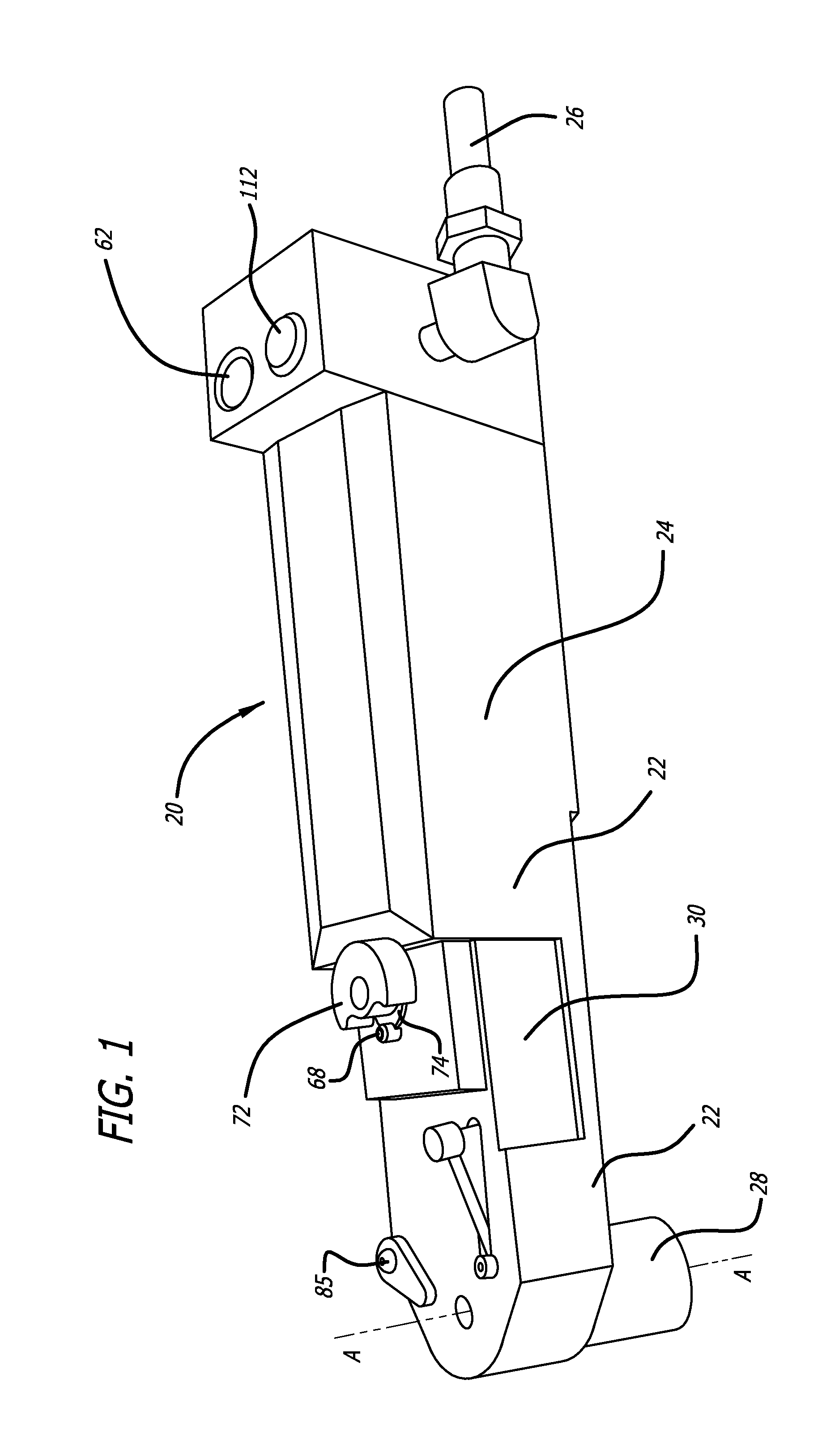
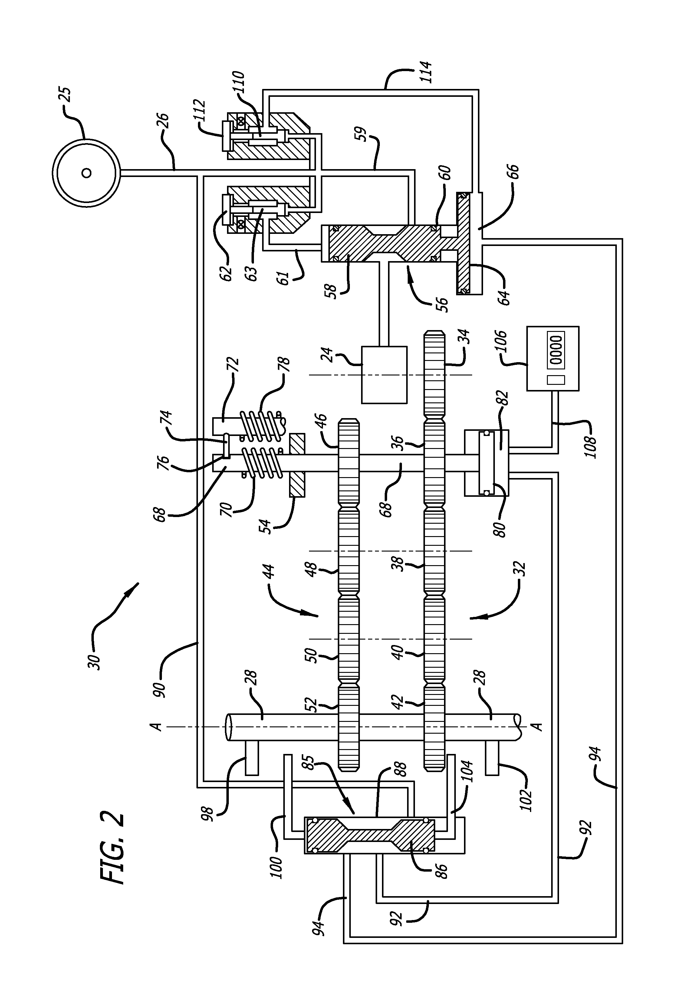
[0027]With reference to FIG. 1, a pneumatic drilling machine, generally referred to by the numeral 20, and method according to a preferred embodiment of the present invention, is described. In general terms, the machine 20 illustrated in the figure is surrounded by a housing 22 and includes a conventional pneumatic motor 24. The motor is connectable to an external source of compressed air 25 (not shown in FIG. 1) through a connector 26. A tool holder spindle 28 held by the housing 22 is adapted to be rotatable about its axis A, and to move the tool back and forth along its axis A. A mechanism 30 for driving the spindle and for controlling the movement of the spindle 28 is located within the housing. Drilling tools can be mounted and removed from the spindle in a conventional ...


PUM

PropertyMeasurementUnit
pressureaaaaaaaaaa
axial displacementaaaaaaaaaa
shapeaaaaaaaaaa

Abstract

A drilling machine is provided for breaking chips formed by drilling action into manageable lengths. The drilling machine comprises a first gear having a first axis of rotation, and a cam follower surface. It has a second gear having a second axis of rotation coincident with the first axis of rotation. A housing is provided configured to support the first gear and the second gear, the housing having a cam surface, a spring and a tool holder spindle having a third axis of rotation. The first and second gears are configured to impart both a linear feed and a rotation to the spindle. The first and second axes of rotation are coincident with the third axis of rotation such that the cam surface is urged into contact with the cam follower surface by the spring. The cam surface and the follower surface are shaped such that when the first gear rotates, the first gear is caused repeatedly to retract and then to advance, breaking chips that are formed.

Description

CROSS-REFERENCES TO RELATED APPLICATIONS[0001]This application is a continuation-in-part of application Ser. No. 11 / 404,298, filed Apr. 14, 2006, which is a continuation of Ser. No. 10 / 951,323 filed Sep. 26, 2004, now U.S. Pat. No. 7,048,077. Applicant claims priority to all of the applications in the chain. These related applications are incorporated herein by reference.FIELD OF THE INVENTION[0002]The present invention relates to the field of drilling machines, more specifically, a system and method applied to drilling machines that has the beneficial result of breaking into short manageable pieces the metal chips that are formed during a drilling operation.BACKGROUND OF THE INVENTION[0003]Power drilling machines are widely used in many industries. One of the troubling problems that grips the industry is the fact that when a helical drill bit is bored into a material it will tend to produce a helically spiraled “chip” of removed material that must find its way out of the hole creat...

Claims


Application Information

Patent Timeline
Patent Type & Authority Patents(United States)
IPC IPC(8): E21B3/00
CPCB23B47/34B23Q5/323B23Q5/326Y10T408/23Y10T408/18Y10T408/165Y10T408/68
Inventor VERES, RICHARD
Owner P V TOOL
Why Eureka
Try Eureka