Configurable lighted connector

a technology of lighted connectors and connectors, applied in the direction of image data processing, coupling device connections, instruments, etc., can solve the problems of increasing the cost of computer systems and the difficulty of connecting users, so as to reduce the number of jacks, simplify the connection of peripheral components, and reduce the cost of devices

Active Publication Date: 2009-03-31
NVIDIA CORP
View PDF24 Cites 3 Cited by
  • Summary
  • Abstract
  • Description
  • Claims
  • Application Information

AI Technical Summary

Benefits of technology

[0010]Advantageously, embodiments simplify connectivity of peripheral components to the device. Embodiments may advantageously reduce the cost of the device by reducing the number of jacks in the device. Embodiments may also advantageously reduce the form factor of the device by reducing the number of jacks in the device. Embodiments may also advantageously free-up area in the device previously occupied by conventional art audio jacks for use by additional circuits in the device.

Problems solved by technology

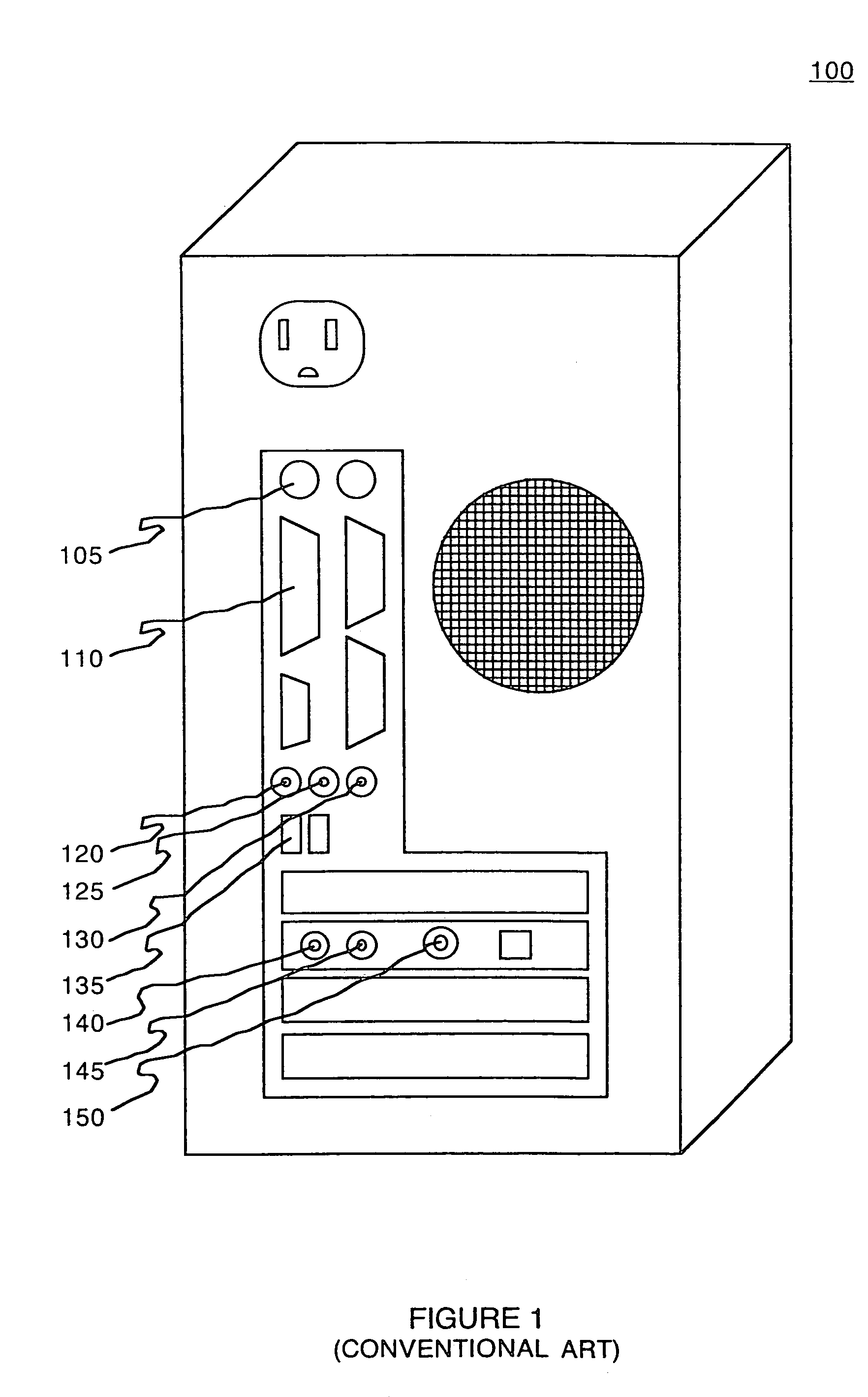
The additional communication connectors 140-150 also increase the cost of the computer system.
Thus, the pre-color communication connectors 105-150 utilized in combination with re-configurability may make connectivity more difficult for users.

Method used


Image

  • Configurable lighted connector
  • Configurable lighted connector
  • Configurable lighted connector

Examples


Embodiment Construction

[0021]Reference will now be made in detail to the embodiments of the invention, examples of which are illustrated in the accompanying drawings. While the invention will be described in conjunction with these embodiments, it will be understood that they are not intended to limit the invention to these embodiments. On the contrary, the invention is intended to cover alternatives, modifications and equivalents, which may be included within the scope of the invention as defined by the appended claims. Furthermore, in the following detailed description of the present invention, numerous specific details are set forth in order to provide a thorough understanding of the present invention. However, it is understood that the present invention may be practiced without these specific details. In other instances, well-known methods, procedures, components, and circuits have not been described in detail as not to unnecessarily obscure aspects of the present invention.

[0022]Referring to FIG. 3A, ...


PUM


Abstract

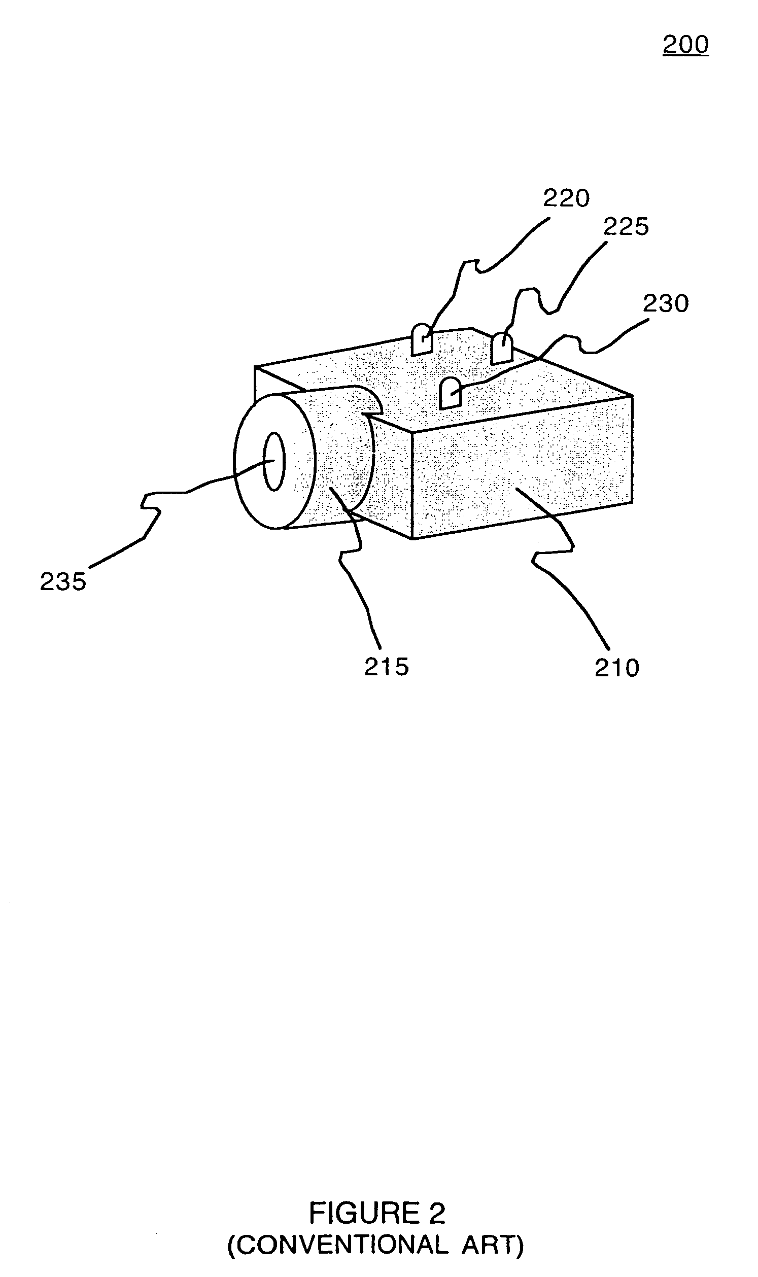
A communication connector, in accordance with one embodiment of the invention, includes an insulative housing having a cylindrical opening, a light source, and a first and second electrical interconnect. The insulative housing includes a body portion and a head portion. The cylindrical opening extends through the head portion and partially into the body portion of the insulative housing. The light source is disposed in the insulative housing proximate the head portion. The first electrical interconnect includes a terminal portion for fixedly connecting the communication connector to a device and a contact portion comprising a resilient conductive element disposed in the cylindrical opening for engaging a mating communication connector. The second electrical interconnect couples an indicator signal to the light source.

Description

[0001]This patent application is a Divisional of commonly-owned patent application Ser. No. 10 / 890,962, filed on Jul. 13, 2004 now U.S. Pat. No. 6,971,907, entitled “CONFIGURABLE LIGHTED CONNECTOR”, by Micah S. Stroud, which is incorporated herein by reference in its entirety.BACKGROUND OF THE INVENTION[0002]Referring to FIG. 1, an electronic device 100 according to the conventional art is shown. The electronic device 100 may be a desktop computer, laptop computer, palm-sized computer, tablet computer, game console, personal entertainment center, media center PC, cellular telephone, PDA or other portable wireless appliance, computer based simulator, or the like. As depicted in FIG. 1, the electronic device 100 includes a plurality of various communication connectors 105-150. The various communication connectors 105-150 are utilized to attach various peripheral components to the device 100. The peripheral components may include speakers, microphones, networks, monitors, printers, key...

Claims


Application Information

Patent Timeline
Patent Type & Authority Patents(United States)
IPC IPC(8): H01R3/00H01R13/66H01R13/717
CPCH01R13/6641H01R13/6691H01R13/7175
Inventor STROUD, MICAH S.
Owner NVIDIA CORP
Why Eureka
Try Eureka