Hard coating film

a technology of hard coating and film, applied in the application, superimposed coating process, natural mineral layered products, etc., can solve the problem of liable to reduce hardness, and achieve the effect of improving high-temperature characteristics

Inactive Publication Date: 2009-03-31
KOBE STEEL LTD
View PDF17 Cites 3 Cited by
  • Summary
  • Abstract
  • Description
  • Claims
  • Application Information

AI Technical Summary

Benefits of technology

[0018]The hard coating film according to the present invention has improved high-temperature characteristics because it is made from CrAl in its nitride (CrAlN) or carbonitride (CrAlCN) form properly combined with Zr and / or Hf. The nitride and carbonitride will be collectively referred to as (carbo)nitride hereinafter.

Problems solved by technology

Although the above-mentioned hard coating films of TiAlN, TiCrAlN, and AlCrN exhibit good oxidation resistance at high temperatures, they are liable to decrease in hardness under harsh conditions involving extremely high temperatures or intense sliding friction (which result from high speed cutting in a dry state or plastic working with a high areal pressure).

Method used


Image

  • Hard coating film
  • Hard coating film
  • Hard coating film

Examples


experiment example 1

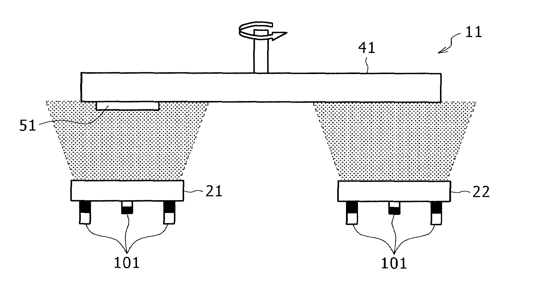
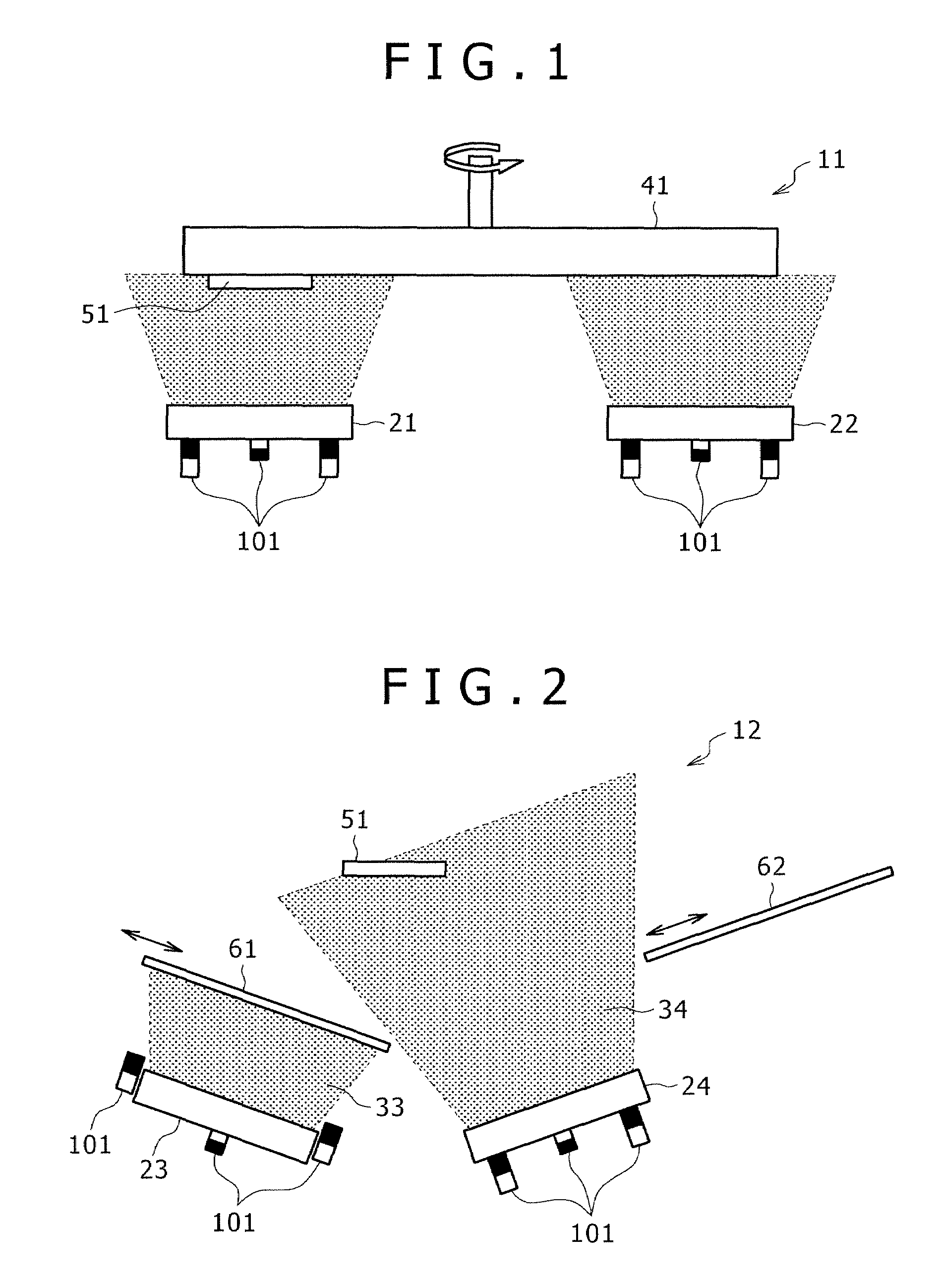
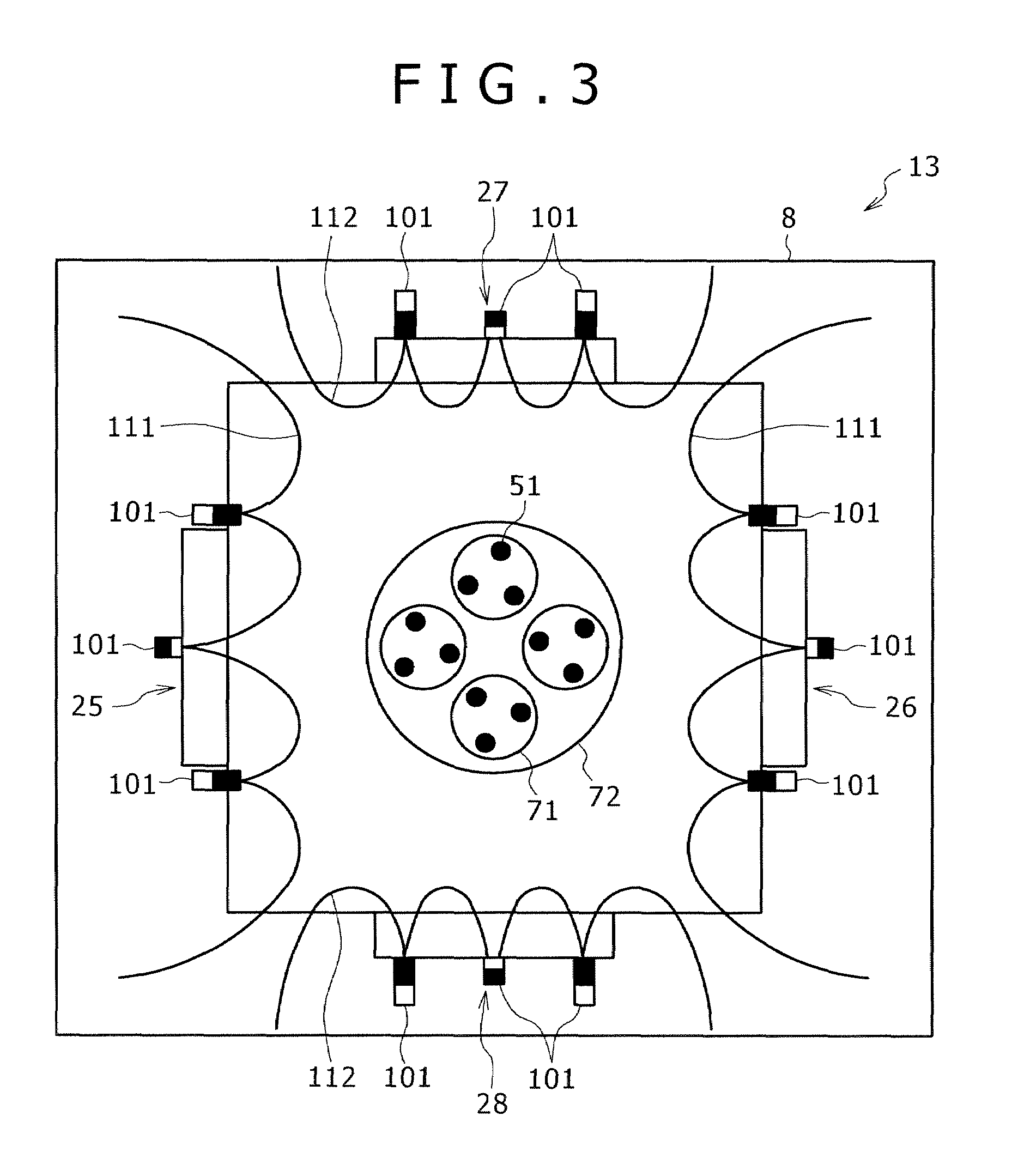
[0088]The apparatus shown in FIG. 3 was used in which the arc evaporation sources 25 and 26 are provided with targets of Cr and Al (whose composition is almost identical with that of the first layer shown in Table 1) and the sputtering evaporation sources 27 and 28 are provided with targets of Zr and Hf (whose composition is almost identical with that of the second layer shown in Table 1). A substrate 51 (tip, ball-nose end mill, or platinum foil), which had been degreased and cleaned with ethanol, was attached to the rotary table 71, and the chamber 8 was evacuated. The system was heated to about 500° C. with a heater (not shown) and the substrate 51 was cleaned with argon introduced into the system, with the rotary plate 72 and the rotary table 71 turning. The film-forming gas (specified below) was introduced and the evaporation sources 25, 26, 27, and 28 were activated to form a hard coating film of laminate type. This procedure was continued until the hard coating film grew to a...

experiment example 2

[0095]The same procedure as Experiment Example 1 was repeated except that the arc evaporation sources 25 and 26 were provided with targets of Cr.Al.Si.B (having almost the same composition as the layer of a first kind shown in Table 2) and the sputtering evaporation sources 27 and 28 were provided with targets of Zr.Hf.Si.B (having almost the same composition as the layer of a second kind shown in Table 1).

[0096]The hard coating film thus obtained exhibited the physical properties shown in Table 2.

[0097]

TABLE 2Layer of a first kindLayer of a second kindComposition of filmComposition of filmCrAlSiBCNThickNessCrystalZrHfNo.(1 − a − b − c)(a)(b)(c)(1 − x)(x)(nm)Structure(1 − k − m − n)(k)iTi0.5Al0.5N3000B1—iiTiCN3000B1—iiiCr0.35Al0.65N3000B1—10.40.350.2500140B41020.40.540.0600140B100.7330.340.66000140B11040.40.570.0300140B11050.40.540.0600140B11060.40.450.1500140B1 + B41070.40.540.0600140B10.96080.40.540.0600140B10.50.4290.40.540.0600140B10.850Layer of a second kindOxidationComposition...

experiment example 3

[0099]The same procedure as Experiment Example 1 was repeated except that the arc evaporation sources 25, 26, 27, and 28 were provided with targets of Cr.Al.Zr.Hf (having almost the same composition as shown in Table 3). (Sputtering evaporation sources were not used.) Deposition was carried out by using N2 gas (having a total pressure of 4 Pa) or a mixture gas of N2 and CH4 (having a partial pressures of 2.7 Pa and 1.3 Pa, respectively for N2 and CH4, and a total pressure of 4 Pa).

[0100]The hard coating film thus obtained exhibited the physical properties shown in Table 3.

[0101]

TABLE 3Composition of filmFilmOxidationWearCrAlZrHfCNCrystalhardnessstartingwidthNo.(1 − p − q − r)(p)(q)(r)(1 − z)(z)structure(HV)temp. (° C.)(μm)iTi0.5Al0.5NB12500850*iiTiCNB12800650**iiiCr0.35Al0.65NB12900100010010.800.2001B1270065010520.750.10.15001B127507009830.40.350.050.201B1300010506540.20.350.20.2501B1320011004550.30.40.3001B13100115047600.500.501B1 + B429508509670.050.650.20.101B1 + B428009508080.05...


PUM

PropertyMeasurementUnit
thicknessaaaaaaaaaa
thicknessaaaaaaaaaa
thicknessaaaaaaaaaa

Abstract

Disclosed herein is a hard coating film of laminate type which comprises more than one layer of a first kind, which has a composition represented by the formula (1a) below and a thickness of 1 to 80 nm, and more than one layer of a second kind, which has a composition represented by the formula (2a) below and a thickness of 1 to 80 nm, the layers being placed alternately one over another.(Cr(1-a)Ala)(C(1-x)Nx)   (1a)(Zr(1-k)Hfk)(C(1-y)Ny)   (2a)where each subscript denotes the atomic ratio specified below.0.2≦a≦0.80.7≦x≦10≦k≦10.5≦y≦1The hard coating film has outstanding high-temperature characteristics.

Description

BACKGROUND OF THE INVENTION[0001]1. Field of the Invention[0002]The present invention relates to a hard coating film that can be advantageously formed on cutting tools (such as tip, drill, and end mill) and jigs (such as forging die and punching die).[0003]2. Description of the Related Art[0004]Conventional cutting tools intended for improved wear resistance consists of a substrate of high speed steel, cemented carbide, cermet, or the like and a hard coating film of TiN, TiCN, TiAlN, and the like formed thereon. Of these hard coating films, that of TiAlN is favorably applied to cutting tools for high speed cutting or hard materials such as hardened steel on account of its very high wear resistance. The recent trend to harder works and higher cutting speed necessitate the development of a new hard coating film with better wear resistance.[0005]An example of recent developments is modification of TiAlN into TiCrAlN (by partial substitution of Ti with Cr) as disclosed in Patent Documen...

Claims


Application Information

Patent Timeline
Patent Type & Authority Patents(United States)
IPC IPC(8): B32B9/00C23C14/06
CPCC23C14/0664C23C14/3464C23C30/005C23C28/044C23C28/42Y10T428/265Y10T428/12576Y10T428/12771Y10T428/12493Y10T428/12743Y10T428/24975Y10T428/26C23C14/00C23C14/34C23C28/00
Inventor YAMAMOTO, KENJI
Owner KOBE STEEL LTD
Why Eureka
Try Eureka