Optical bench having V-groove for aligning optical components

a technology of optical components and alignment members, which is applied in the field of optical assembly to achieve the effects of accurate positioning of an opto-electric device, reducing environmental changes and manufacturing tolerances, and reducing the effect of inter-component effects

Inactive Publication Date: 2009-03-31
TE CONNECTIVITY CORP
View PDF9 Cites 36 Cited by
  • Summary
  • Abstract
  • Description
  • Claims
  • Application Information

AI Technical Summary

Benefits of technology

[0010]The TPB of the present invention and its manufacture have a number of important advantages over the prior art. First, since the V-groove has register surfaces along the x and y-axes, it provides for xy alignment. This is a significant advantage over prior art optical benches, such as platforms and rails, which tend to provide alignment along either the x or y axis, but not both. Furthermore, xy passive alignment is particularly valuable since it tends to be difficult to achieve than z alignment.
[0011]Not only does the TPB of the present invention provide for xy alignment, but the mechanism it uses to effect alignment is particularly robust. That is, since the optical components are mounted to a common surface, the TPB is more tolerant of environment changes and manufacturing tolerances. For example, if the TPB is exposed to significant temperature swings, the effect of dimensional variations of the TPB will be mitigated since all of the optical components are mounted on the same surface. In other words, any changes will affect all the components equally. Additionally, if the V-groove is subject to manufacturing variations, the inter-component effects will again be minimized since all the components will be affected similarly. For example, if the V-groove is etched more narrowly, the optical components will all seat higher relative to the bottom of the V-groove.
[0012]Yet another advantage of the TPB of the present invention is the precision it affords. Specifically, techniques have been developed for forming V-grooves in substrates to exacting tolerances. This is significant not only with respect to the main V-groove, but also with respect to the first optical component. Specifically, the substrate of the first optical component is preferably formed by etching parallel V-grooves into a wafer and then parting the wafer along the V-grooves to form the substrate. Thus, the dimensions of the substrate are defined using V-grooves which, as mentioned above, are extremely accurate.
[0013]The present invention also allows for extremely accurate positioning of an opto-electric device on the substrate of the first optical component. Specifically, the V-grooves and the solder pads for the opto-electric device can be located on the wafer in one step using well-known photolithography techniques. The ability to do both at the same time is important since the distance from the optical axis of the opto-electric device and the sides of the substrate is critical. Defining the solder pads in effect defines the position of the opto-electric device on the substrate since the surface tension of the solder pads will tend to pull the device over them during reflow. This is a well-known technique. Thus, the preparation technique of the present invention not only defines the dimensions of the substrate accurately using V-groove techniques, but also defines the position of the solder pads (and thus the optoelectric device) precisely with respect to the sides of the substrate. (Although the present invention realizes certain advantages over prior art techniques in manufacturing an opto-electric first optical component, it should be understood that the invention is not limited to an opto-electric first optical component.)

Problems solved by technology

Furthermore, xy passive alignment is particularly valuable since it tends to be difficult to achieve than z alignment.

Method used


Image

  • Optical bench having V-groove for aligning optical components
  • Optical bench having V-groove for aligning optical components
  • Optical bench having V-groove for aligning optical components

Examples


Embodiment Construction

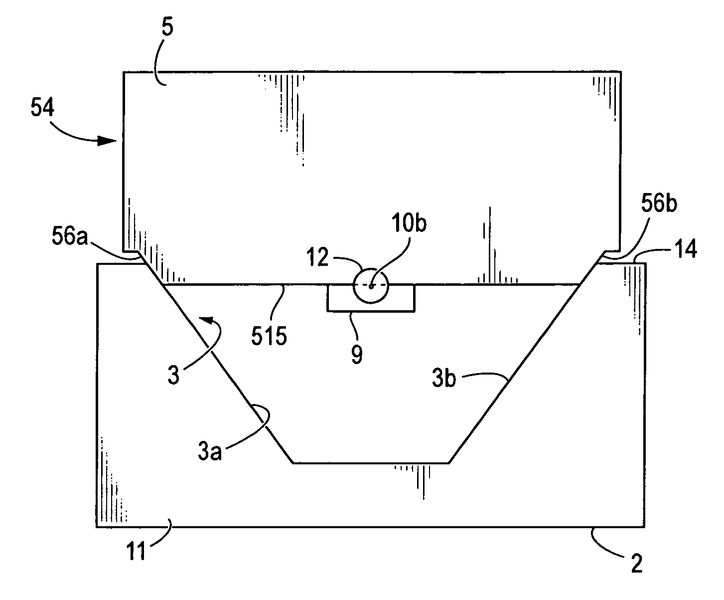
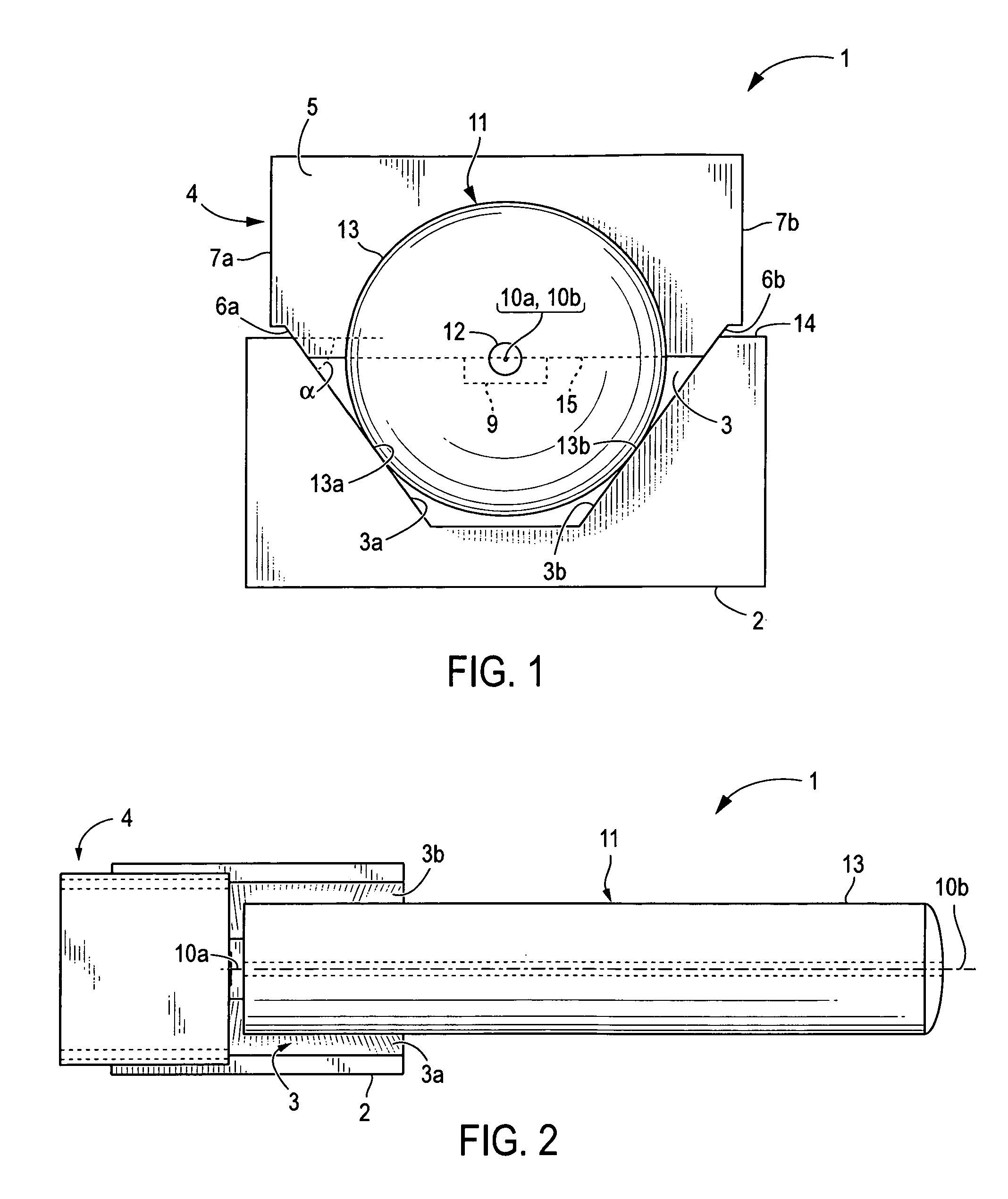
[0020]Referring to FIGS. 1 and 2, side and top views, respectively, are shown of an optical assembly 1 using the optical true position bench (TPB) approach of the present invention. The optical assembly 1 comprises a platform 2 for holding first and second optical components 4, 11 in optical alignment. Although the optical assembly shown in FIG. 1 and described herein comprises just two optical components, it should be understood that the invention is not limited in the number of optical components which may be held and aligned in the platform 2. For purposes of simplicity and to facilitate understanding, however, this description will focus on an assembly comprising just two optical components.

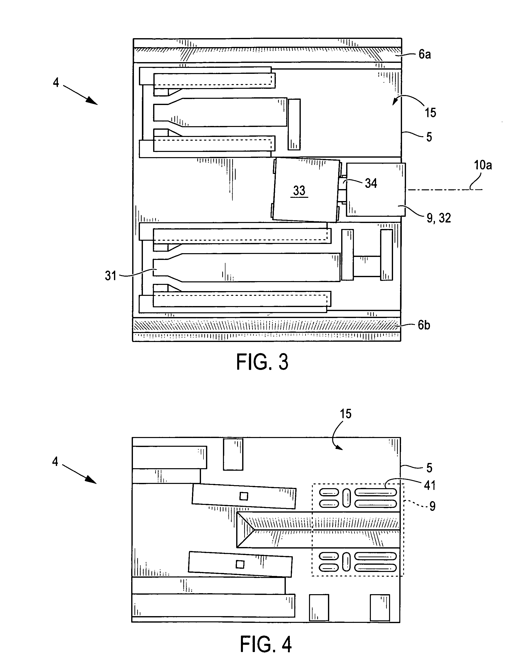
[0021]The platform defines a V-groove 3 with walls 3a, 3b of a certain pitch α. A first optical component 4 is disposed in the V-groove 3. The first optical component 4 has a first optical axis 10a, a reference surface 15 and two sides 6a, 6b, each side is beveled at the certain pitch α outwa...


PUM


Abstract

An optical package having a top and bottom orientation and comprising: (a) a platform defining a V-groove with walls of a certain pitch; (b) a first optical component having a reference surface and two sides, each side being beveled at the certain pitch outwardly from the reference surface, the first optical component having a first optical axis, the first optical component being disposed in the V-groove such that the reference surface faces downward and the sides are in parallel contact with the walls of the V-groove; and (c) a second optical component having an outer periphery with at least two contact points and a second optical axis, the second optical component being disposed in the V-groove such that the contact points contact the walls of the V-groove and the second optical axis is coaxial with the first optical axis.

Description

REFERENCE TO RELATED APPLICATION[0001]This application claims priority to U.S. Provisional Application No. 60 / 393,486 filed on Jul. 3, 2002 and hereby incorporated by reference.FIELD OF INVENTION[0002]This invention relates generally to an optical assembly, and, more specifically, to an optical assembly having an alignment member for optically aligning its components.BACKGROUND[0003]The use of optical fibers as a medium for transmission of digital data (including voice data) is becoming increasingly more common due to the high reliability and large bandwidth available with optical transmission systems. Fundamental to these systems are optical assemblies for transmitting / receiving optical signals and multiplexing / demultiplexing signals. The manufacture of these optical assemblies, however, tends to be difficult, expensive, and time consuming.[0004]One of the primary technical challenges associated with the manufacture of optical assemblies, especially systems offering higher levels o...

Claims


Application Information

Patent Timeline
Patent Type & Authority Patents(United States)
IPC IPC(8): H01J3/14G02B6/26G02B6/36G02B6/42H01L31/0232H01S5/022
CPCG02B6/3636G02B6/4202G02B6/4206G02B6/4224G02B6/423G02B6/4232G02B6/3692
Inventor BOWEN, TERRY P.PERKO, RICHARD J.BREEDIS, JOHN B.
Owner TE CONNECTIVITY CORP
Why Eureka
Try Eureka