Thermal enhanced low profile package structure

Active Publication Date: 2009-03-31
IND TECH RES INST
View PDF9 Cites 59 Cited by
  • Summary
  • Abstract
  • Description
  • Claims
  • Application Information

AI Technical Summary

Problems solved by technology

Nevertheless, there still exists an important issue worthy to be mentioned in view of the thermal dissipation inside the package structure.

Method used


Image

  • Thermal enhanced low profile package structure
  • Thermal enhanced low profile package structure
  • Thermal enhanced low profile package structure

Examples


Embodiment Construction

[0042]The present invention will now be described more specifically with reference to the following embodiments. It is to be noted that the following descriptions of preferred embodiments of this invention are presented herein for purpose of illustration and description only; it is not intended to be exhaustive or to be limited to the precise form disclosed.

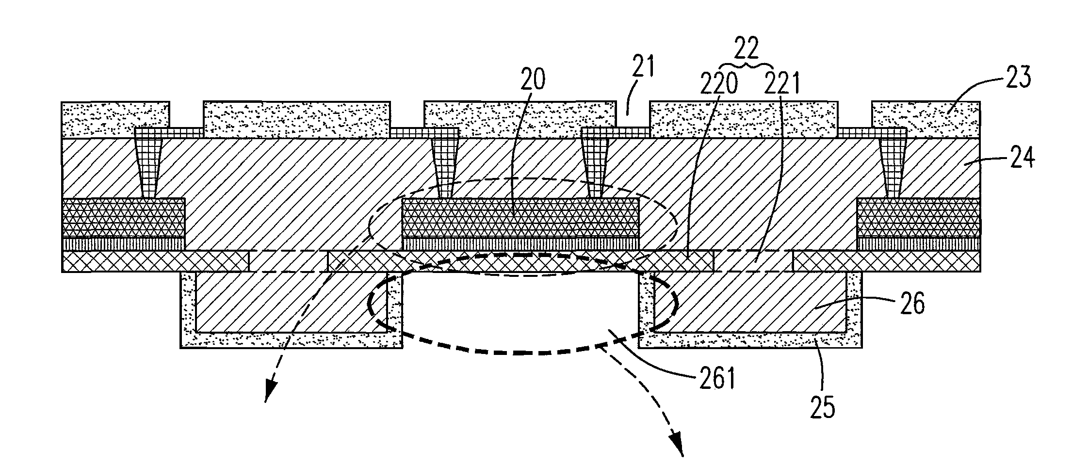
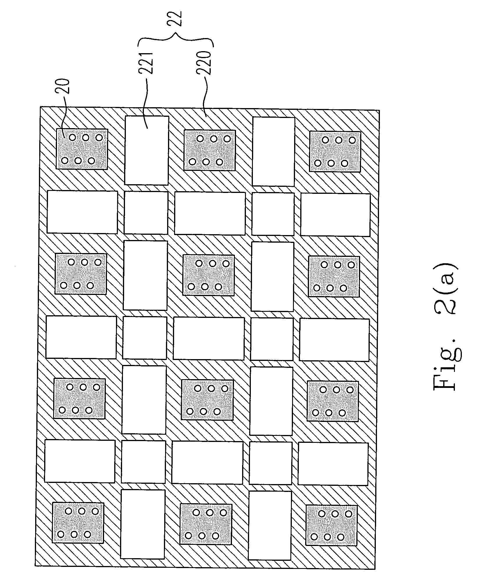
[0043]Please refer to FIGS. 2(a) to 2(h), which schematically illustrate the method for fabricating the thermal enhanced low profile package structure of the present invention. First, the electronic component 20 to be packaged is placed on a provided leadframe-like carrier 22. The electronic component 20 may be a die. As shown in FIG. 2(a), there are plural channels 221 formed on the leadframe-like carrier 22, so that the leadframe-like carrier 22 is divided into plural lead carriers 220. The electronic component 20 is located correspondingly to one of the lead carriers 220.

[0044]Then, a first dielectric layer 24, and a second di...


PUM


Abstract

A thermal enhanced low profile package structure and a method for fabricating the same are provided. The package structure typically includes a metallization layer with an electronic component thereon which is between two provided dielectric layers. The metallization layer as well as the electronic component is embedded and packaged while the substrates are laminated via a lamination process. The fabricated package structure performs not only a superior electric performance, but also an excellent enhancement in thermal dissipation.

Description

FIELD OF THE INVENTION[0001]The present invention relates to an electronic package structure and a method for fabricating the electronic package structure, and more particularly, to a thermal enhanced low profile electronic package structure and a method for fabricating it.BACKGROUND OF THE INVENTION[0002]For the trend toward the miniaturization for the electronic device, the electronic manufacturers involved in the technology have made more and more efforts in manufacturing a portable and miniature electronic device with a great functionality and operation density. Since an electrical connection between the circuit in the package structure for an electronic device and the integrated circuit (IC) chip applied therein must be well made for being operated with a high efficiency, an increasing development is also necessary for the electronic package technology to provide a package structure having the improved functionalities of electricity conducting, signal transferring, thermal diss...

Claims


Application Information

Patent Timeline
Patent Type & Authority Patents(United States)
IPC IPC(8): H01L23/495H01L23/48H01L23/52H01L29/40H05K1/16
CPCH01L21/56H01L21/561H01L23/3107H01L23/3128H01L23/4334H01L23/49568H01L24/19H01L24/20H01L24/97H01L2224/04105H01L2224/20H01L2224/32188H01L2224/73267H01L2224/97H01L2924/01029H01L2924/01082H01L2924/14H01L2924/15311H01L2924/19041H01L2924/19042H01L2924/19043H01L2924/30105H01L2924/30107H01L2224/82H01L2924/01005H01L2924/01006H01L2924/01033H01L2224/82039H01L2224/92244H01L2224/32245H01L2224/83
Inventor WU, ENBOACHEN, SHOU-LUNG
Owner IND TECH RES INST
Why Eureka
Try Eureka