Vehicle back-up viewing system

a viewing system and vehicle technology, applied in the field of vehicle backup viewing system, can solve the problems of display blank or black screen, unpowered, etc., and achieve the effect of simple installation

Active Publication Date: 2009-03-31
D LARRY HUBBARD +1
View PDF19 Cites 173 Cited by
  • Summary
  • Abstract
  • Description
  • Claims
  • Application Information

AI Technical Summary

Benefits of technology

[0006]The present inventor has recognized that there exists a need to provide a low-cost, simple to install, vehicle back-up viewing system to aid operators of vehicles that do not currently contain such a system. There also exists a need for a system where a vehicle owner with little or no automotive skills can install the system. Additionally, there exists a need for a system that can be installed without the need to run wires from the rear of the vehicle to the area from which the vehicle is operated.
[0007]In view of the foregoing, one objective of the present invention is to provide a vision system and method to display to a vehicle operator at least one view of the exterior of the vehicle to enhance visibility and safety while also being simple to use and install. In the later regard, a related objective of the present invention is to provide an improved method of installing a vehicular vision system.
[0008]The above-noted objectives and additional advantages are realized in the present invention. To do so, a vehicular vision system is provided where the camera is powered by electrically connecting a portion of the system to a reverse lamp power line that powers the vehicle's external reverse lamps. To avoid negatively affecting the performance of the vehicle's external reverse lamps, the system should preferably draw less than a predetermined maximum amount of electrical power. Also, the inventor has realized that there exists a need for a low cost vehicle back up viewing system and therefore has developed the present system which has a minimal amount of components and is relatively simple to install. In the latter regard, the system may include a wireless connection between the camera and display, reducing the amount of wiring needed to install the system and further simplifying the system installation process. As a result, the invention is particularly well suited for rapid installation by automotive professionals as well as for installation by vehicle owners.

Problems solved by technology

When the camera is not actively capturing images, the display may display a blank or black screen or be unpowered.

Method used


Image

  • Vehicle back-up viewing system
  • Vehicle back-up viewing system
  • Vehicle back-up viewing system

Examples


Embodiment Construction

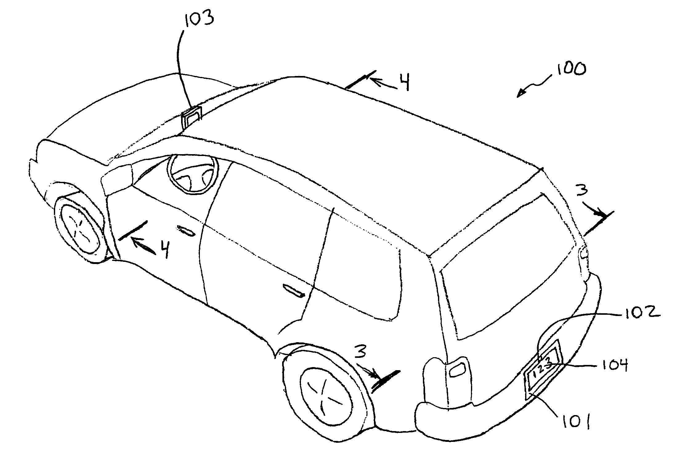
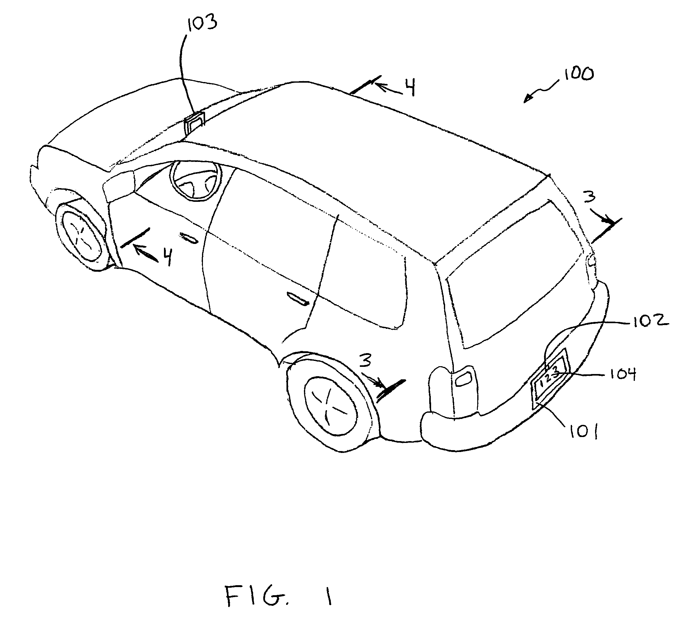
[0042]FIGS. 1-6 illustrate one embodiment of the present invention. The illustrated embodiment provides a license plate frame mounted rear facing camera and a dashboard mounted display unit to provide a vehicle operator or driver with a video display of the area immediately behind the vehicle. As will be appreciated, various features of the illustrated embodiment may be implemented in other embodiments within the scope of the present invention, including for example embodiments which provide for cameras pointed in other directions and mounted by other means and displays mounted in other locations and mounted by other means.

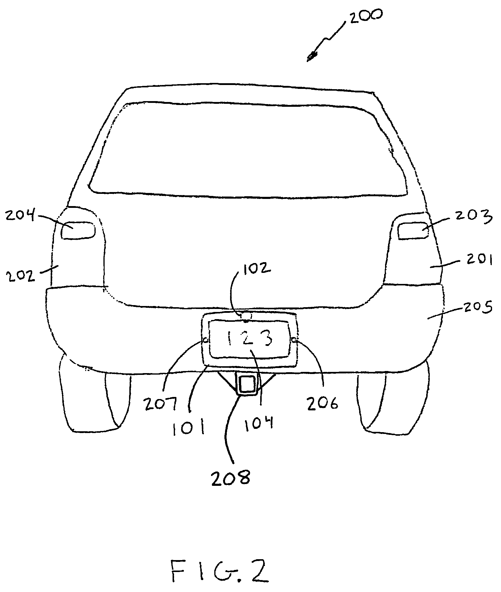
[0043]FIG. 1 is a perspective view of an embodiment of the present invention. Mounted to a vehicle 100 is a license plate 104 located within a license plate frame 101. Connected to the license plate frame 101, is a small camera 102. The camera 102 may be configured to capture images of the area immediately behind the vehicle. The camera 102 may be capable of captu...


PUM


Abstract

A system for displaying an external view of a vehicle is provided. The system may comprise a video camera for capturing images external to the vehicle and a display for displaying the images for the vehicle operator. The camera is powered by electrically connecting it to the reverse lamp power line and is operable to continuously capture images when powered. The camera may be mounted in a license plate frame to further simplify installation. The camera may communicate with the display through a wireless connection. The receiver and display may be mounted in the field of view of the vehicle operator, such as on the dashboard of the vehicle.

Description

FIELD OF THE INVENTION[0001]The present invention generally relates to vision systems to assist vehicle operators and related methods of operation and installation. The invention is particularly apt for providing, in a low-cost, easy to install system, the driver of a vehicle with a view of the area immediately behind the vehicle from a rear facing camera mounted on the vehicle.BACKGROUND OF THE INVENTION[0002]Many vehicles, such as currently popular SUVs and minivans do not provide the driver with adequate views of the areas immediately behind and around the vehicle. To overcome this deficiency, vehicle designers and users have developed devices such as wide-angle mirrors and proximity sensors to help drivers identify any hazards that may be in proximity to the vehicle. Recently, vision systems utilizing remote cameras and displays have been incorporated to aid drivers in identifying these hazards.[0003]Consequently, the use of vision systems to assist vehicle operators by displayi...

Claims


Application Information

Patent Timeline
Patent Type & Authority Patents(United States)
IPC IPC(8): B60Q1/00G08G1/00
CPCB60Q9/005B60R1/00B60R11/04B60R13/105G08G1/16G08G1/168H04N5/23241H04N7/18B60R11/0235B60R2300/302B60R2300/404B60R2300/406B60R2300/806H04N23/65
Inventor HUBBARD, D. LARRYSMOLENSKI, RICHARD
Owner D LARRY HUBBARD
Why Eureka
Try Eureka