Eureka AIR delivers breakthrough ideas for toughest innovation challenges, trusted by R&D personnel around the world.

Device for improving the life of a triaxial gyro

Active Publication Date: 2009-03-31
THALES SA
View PDF24 Cites 4 Cited by
  • Summary
  • Abstract
  • Description
  • Claims
  • Application Information

AI Technical Summary

Benefits of technology

[0018]The subject of the present invention is a device for improving the life of a triaxial gyro in the simplest and most inexpensive way possible.

Problems solved by technology

As is known in the state of the art, one limitation to the life of a laser gyro is directly linked to the operating time of the cathode.
This operating time is limited by the sputtering of the oxide layer deposited on the cathode.
For an application requiring a very long life, this configuration is limited by the fact of the high current density required of the cathode, as specified above.

Method used


Image

  • Device for improving the life of a triaxial gyro
  • Device for improving the life of a triaxial gyro
  • Device for improving the life of a triaxial gyro

Examples


Embodiment Construction

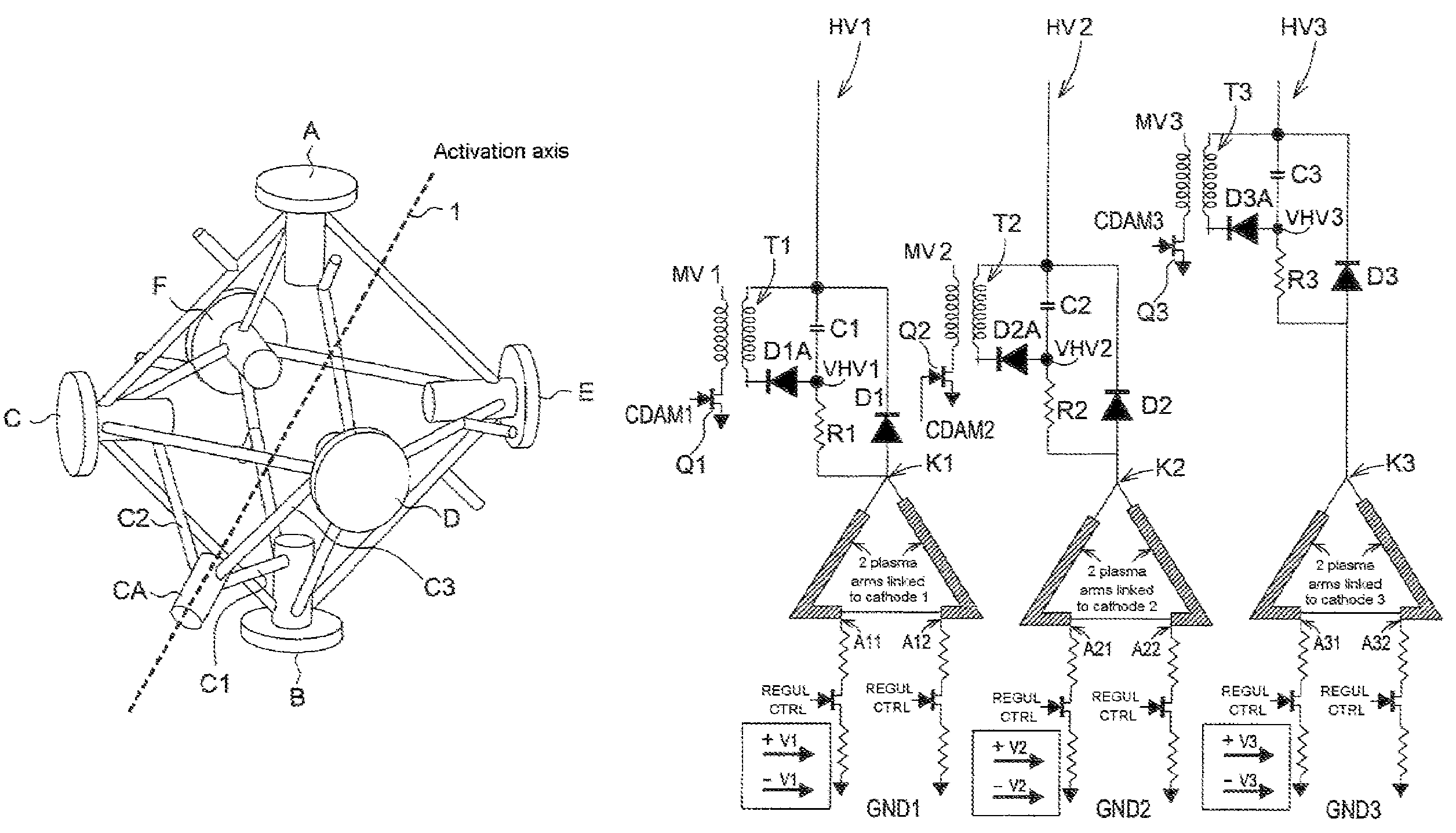
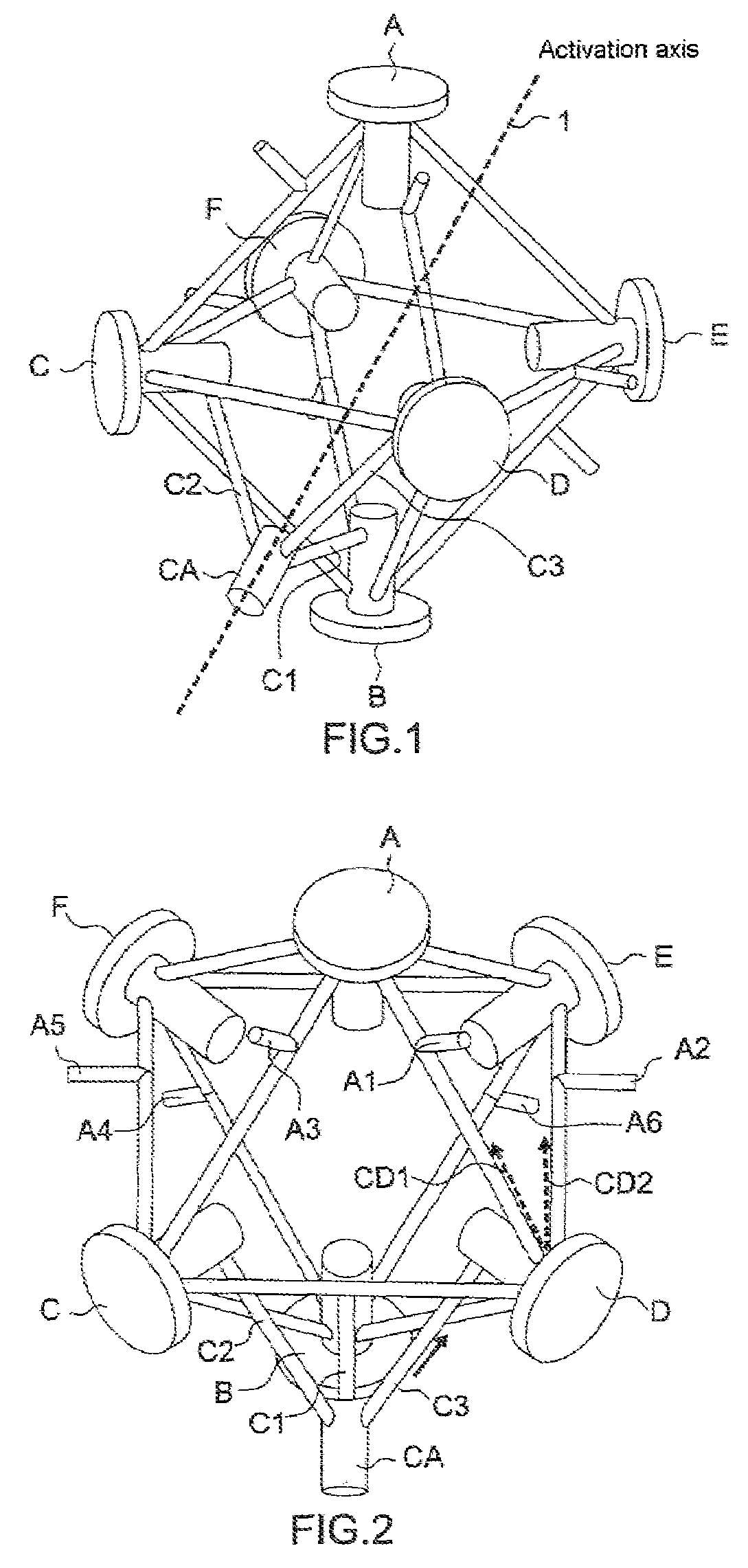
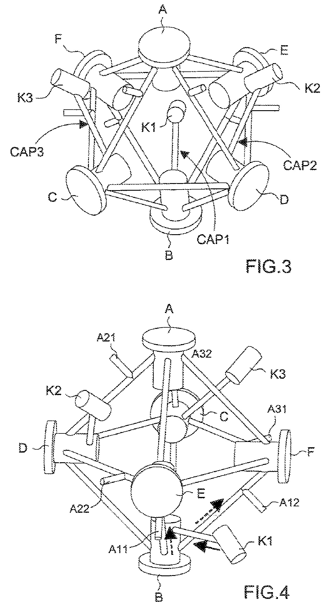
[0028]One of the main characteristics of the inventive gyro is that it comprises three cathodes, each supplying two anodes, in order to very significantly reduce the current density passing through each cathode. Consequently, this configuration entails modifying the current regulation and the ignition sequence of the gyro. The description below refers to the gyro of the prior art, as represented in FIGS. 1 and 2, for the parts that are common with those of the inventive gyro, and only the novel elements of the latter will be described in detail.

[0029]In the inventive gyro with optical block with three cathodes, each cathode (K1 to K3) is linked by a capillary (CAP1 to CAP3 respectively) to one of the three gas reserves associated with the mirrors B, C, D as shown in FIGS. 3 and 4. From each gas reserve, as in the gyro of the prior art, two capillaries leave towards two anodes. Thus, as shown in FIG. 4, the cathode K1 supplies the plasmas of the anodes A11 and A12. Similarly, the cat...


PUM


Abstract

The present invention relates to a laser gyro of the type comprising an optical block comprising three communicating resonant optical cavities which form a regular octahedron having eight triangular sides, each of the cavities presenting four capillary segments forming a square perpendicular to a corresponding sensitive axis, these cavities being arranged so that each of the angles of one cavity coincides and communicates with the angle of another cavity, a mirror associated with each pair of coinciding angles being oriented so as to be used by the two cavities forming said pair, each cavity using four mirrors including a reading mirror and a cavity-length servo mirror, said gyro also comprising an activation mechanism for driving the block according to a reciprocating rotation movement about an activation axis, and it is characterized in that this gyro comprises three cathodes each linked to two cavities out of the three, these two cavities being each time taken by circular permutation.

Description

RELATED APPLICATIONS[0001]The present application is based on, and claims priority from, France Application Number 0605666, filed Jun. 23, 2006, the disclosure of which is hereby incorporated by reference herein in its entirety.FIELD OF THE INVENTION[0002]The present invention relates to a device for improving the life of a triaxial gyro.BACKGROUND OF THE INVENTION[0003]As is known in the state of the art, one limitation to the life of a laser gyro is directly linked to the operating time of the cathode. This operating time is limited by the sputtering of the oxide layer deposited on the cathode. For one considered cathode geometry, the life is mainly dependent on the current density required of the cathode.[0004]The main characteristics of a triaxial gyro will first be reviewed. The current configuration of such a gyro (FIG. 1) uses a system of plasma discharges which leaves from a single cathode (CA) and is then split by passing into three linking capillaries (C1 to C3) which arri...

Claims


Application Information

Patent Timeline
IPC IPC(8): G01C19/66H01S3/083
CPCG01C19/668
Inventor BONNAUDET, ETIENNEGALLON, PIERREDAVID, SELVIN
Owner THALES SA
Why Eureka
Eureka Blog
Learn More