Sole structure for a shoe

a technology for shoe soles and forefoot, which is applied in the direction of fastenings, footwear, apparel, etc., can solve the problems of affecting achieve the effect of improving the bendability of the sole forefoot portion, preventing further supination of the foot on the ground, and being easily and immediately introduced into the inside of the sho

Active Publication Date: 2009-04-07
MIZUNO CORPORATION
View PDF8 Cites 58 Cited by
  • Summary
  • Abstract
  • Description
  • Claims
  • Application Information

AI Technical Summary

Benefits of technology

[0007]According to the present invention, during bending deformation of the sole forefoot portion, the lower plate having a longer longitudinal path than the upper plate does not hinder the bending deformation of the sole forefoot portion, thereby increasing the bendability of the sole forefoot portion.
[0023]There may be provided a cushion pad at a position corresponding to the cleat between the upper plate and the lower plate. In this case, the cushion pad can absorb and relieve the pressure applied by the cleat from below to the sole.

Problems solved by technology

To the contrary, in the case where the length of the path of the lower plate in the longitudinal direction is shorter than or equal to the length of the path of the upper plate in the longitudinal direction, during bending deformation of the sole forefoot portion, the lower plate restricts the deformation of the upper plate, thus hindering the bendability of the sole forefoot portion.

Method used


Image

  • Sole structure for a shoe
  • Sole structure for a shoe
  • Sole structure for a shoe

Examples


first embodiment

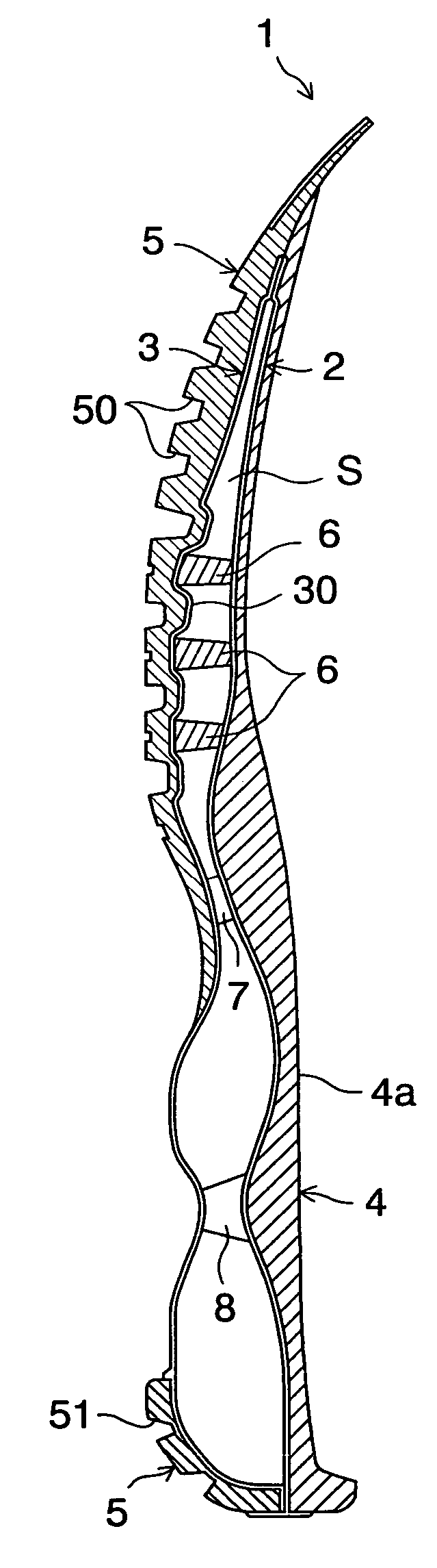
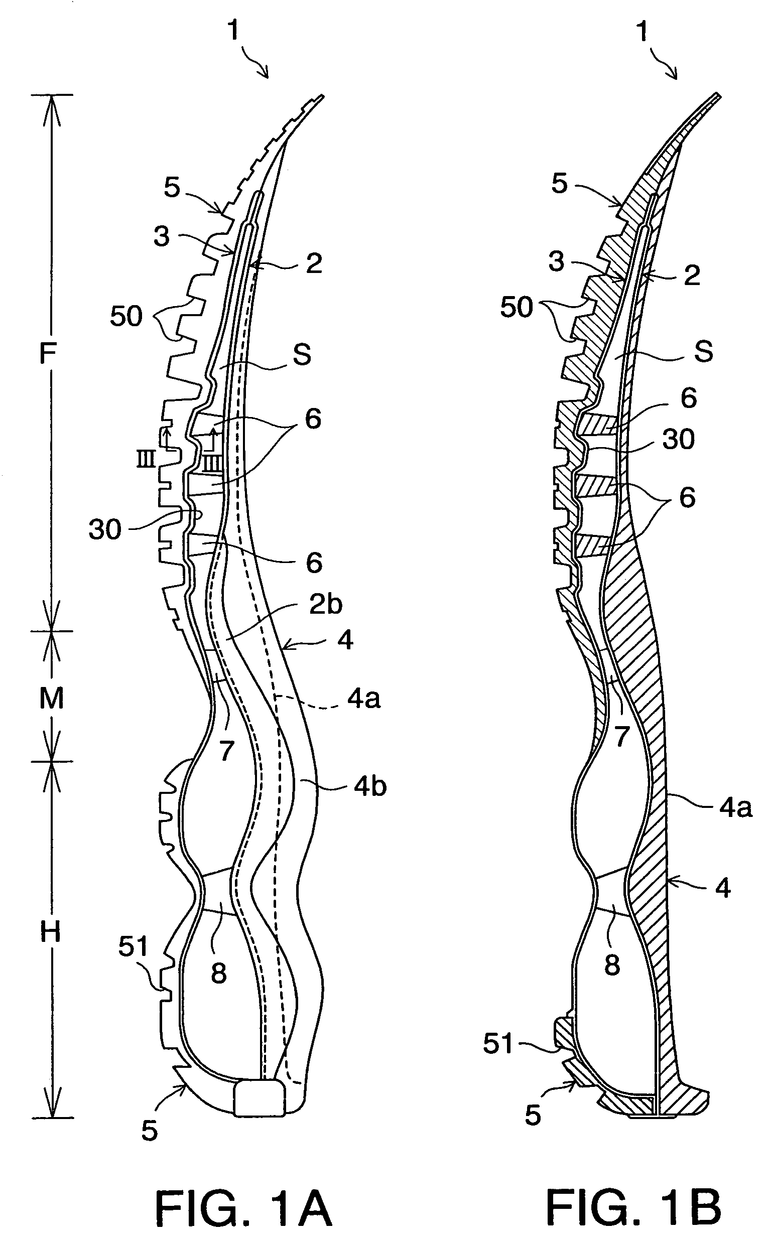
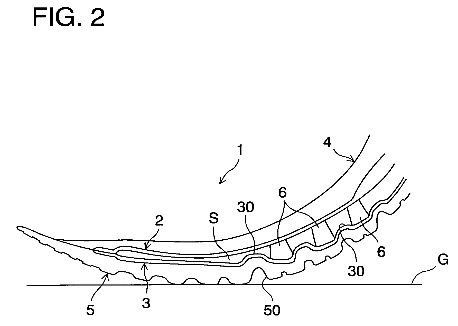
[0042]Referring now to the drawings, FIGS. 1A and 1B show a sole structure according to the present invention. The sole structure 1 for a shoe includes an upper plate 2 extending from the heel portion H through the midfoot portion M to the forefoot portion F, and a lower plate 3 disposed below the upper plate 2 and extending from the heel portion H through the midfoot portion M to the forefoot portion F. A void S is formed between the upper plate 2 and the lower plate 3. The upper and lower plate 2, 3 extend in the shoe width direction (or into the page of FIG. 1A) as well.

[0043]Above the upper plate 2 is provided a midsole 4 formed of a soft elastic material and extending from the heel portion H through the midfoot portion M to the forefoot portion F. The upper plate 2 is fixedly attached to the bottom surface of the midsole 4. The midsole 4 has a foot contact surface 4a that contacts the sole of a shoe wearer's foot and an upraised portion 4b formed at opposite side edges of the f...

second embodiment

[0072]FIGS. 5A and 5B show a sole structure according to the present invention. In these drawings, like reference numbers indicate identical or functionally similar elements.

[0073]As with the sole structure 1 of the above-mentioned first embodiment, the sole structure 1′ according to the second embodiment has the upper and lower plate 2, 3 extending from the heel portion H to the forefoot portion F and located away from each other via the void S. The sole structure 1′ differs from the sole structure 1 in that the upper plate 2 of the sole structure 1′ has a plurality of convex portions 20 protruding toward the lower plate 3 in the central region to the rear region of the forefoot portion F. These convex portions 20 protrude toward the position between the longitudinally adjacent convex portions 30 of the lower plate 3.

[0074]In the case as well where not only the lower plate 3 but also the upper plate 2 has the convex portions, similar to the first embodiment, the longitudinal path l...

third embodiment

[0079]FIG. 6 shows a lower plate of the present invention. As shown in FIG. 6, the lower plate 3 has a longitudinally extending indentation 35 formed centrally in the forefoot region.

[0080]In this case, the medial and lateral portions of the lower plate 3 disposed on opposite sides of the indentation 35 can deform downwardly independently of the other portion, thus improving the lateral bendability of the sole forefoot portion. In this case, a sole structure can be achieved that is suitable for sports such as tennis, basketball or the like where side steps are required.

[0081]The position of the indentation 35 is not limited to the laterally central position of the lower plate 3, and it may be located at the position either closer to the medial side (i.e. the great toe side) or the lateral side (i.e. the little toe side). Also, by properly adjusting the width and number of the indentation 35, the way of deformation of the medial portion and the lateral portion of the lower plate 3 ca...


PUM

PropertyMeasurementUnit
angleaaaaaaaaaa
bending angleaaaaaaaaaa
longitudinal path lengthaaaaaaaaaa

Abstract

A sole structure is provided that can improve bendability and cushioning ability of the sole forefoot portion. The sole assembly 1 is formed of an upper plate 2, and a lower plate 3 provided below the upper plate 2 and spaced apart from the upper plate 2 via a void S. The lower plate 3 has a plurality of protrusions 30 that protrude toward the upper plate 2. The longitudinal path length L1 of the lower plate 3 is longer than the longitudinal path length L2 of the upper plate 2. More specifically, the path length L1 of the lower plate 3 is 40-60% longer than the path length L2 of the upper plate 2.

Description

BACKGROUND OF THE INVENTION[0001]The present invention relates generally to a sole structure for a shoe, and more particularly, to an improvement in the sole structure for enhancing cushioning properties and bendability of the forefoot portion of the sole.[0002]Japanese patent application laying-open publication No. 2003-339405 shows a sole structure for a shoe to secure cushioning properties and improve bendability. The sole structure shown in this publication has a structure in which an upper plate and a lower plate are disposed on the upper side and the lower side, respectively, of a wavy plate that extends from the heel region to the forefoot region.[0003]In this case, a plurality of voids formed between the wavy plate and the upper and lower plate provide cushioning properties. Also, in this case, the wavy plate has a two-layered shank portion of a spindle shape in the sole midfoot portion. Such a shank portion restrains bending deformation of the sole midfoot portion, thus imp...

Claims


Application Information

Patent Timeline
Patent Type & Authority Patents(United States)
IPC IPC(8): A43B13/28A43B13/18
CPCA43B13/12A43B13/141A43B13/181A43B13/20A43C15/02A43C15/168
Inventor KITA, KENJIROMIYAUCHI, AKIHIROITO, KOJI
Owner MIZUNO CORPORATION
Why Eureka
Try Eureka