Temperature measuring device and regulation of the temperature of hot gas of a gas turbine

a technology of temperature measurement device and gas turbine, which is applied in the direction of engines, mechanical equipment, machines/engines, etc., to achieve the effect of reliable and high-performance operation of gas turbine, avoiding both overfiring and underfiring of gas turbin

Active Publication Date: 2009-04-07
SIEMENS ENERGY GLOBAL GMBH & CO KG
View PDF7 Cites 88 Cited by
  • Summary
  • Abstract
  • Description
  • Claims
  • Application Information

AI Technical Summary

Benefits of technology

[0015]In an advantageous refinement, the air temperature and humidity distributions can be predetermined in the form of diagrams, so that it is particularly simple to portray the dependency of the evaporation of the injected liquid in the air stream. This contributes to simple calculation.
[0019]In an advantageous configuration of the control arrangement, with 100% evaporation a minimum possible temperature is determined and used as replacement for the temperature at the inlet of the compressor. In this context, it is assumed that the liquid introduced by the injection apparatus evaporates sufficiently for a relative air humidity of 100% to be established at the compressor inlet. Working on the basis of this assumption, it is possible, in conjunction with the measured air humidity and air temperature, to determine the minimum feasible (lowest possible) temperature at the compressor inlet. If the minimum possible temperature is now used as the temperature for the air stream at the compressor inlet, the temperature which actually prevails at the compressor inlet is always greater than the minimum possible temperature, since an air humidity of 100% is never achieved without external action. In this situation, the gas turbine is always underfired. Overheating of the components exposed to hot gas is therefore avoided, so that the service life of the components is not reduced.
[0020]An improved control arrangement for the gas turbine ensues if the temperature of the air stream at the inlet of the compressor is calculated taking account of the actual evaporation of the injected liquid in the air stream. The efficiency of the evaporation is determined by calculations and / or tests, and this efficiency, with the aid of the minimum possible temperature, is used to determine the air temperature which is present at the compressor inlet. With this control arrangement, it is possible to reproduce the true conditions with regard to evaporation of the introduced liquid on the way to the compressor inlet, and thereby to bring about reliable and more high-performance operation of the gas turbine, avoiding both overfiring and underfiring of the gas turbine.
[0021]In a preferred configuration of the control arrangement, the quantity of liquid injected into the air stream is altered as a function of the evaporation. The compressors of gas turbines are usually dimensioned for a predetermined quantity of liquid which evaporates during the compression. However, the evaporation causes a small proportion of the injected liquid to evaporate even before the compression, which means that the compressor is not operated in the optimum range. This drawback can be avoided by adapting the quantity of liquid injected.
[0022]The efficiency of the evaporation, which is substantially dependent on the droplet characteristics and the geometry, i.e. the spatial arrangement of the components of a compressor, can be estimated from tests and / or determined from calculations, which are then stored in the form of models or formulae in the controller. The avoidance of underfiring increases the power output of the gas turbine, and the prevention of overfiring of the gas turbine means that the service life of the components which guide hot gas is not adversely affected.

Problems solved by technology

Therefore, the liquid which is introduced cannot wet the temperature-measuring devices, which means that it is always the temperature of the air stream that is sucked in which is measured.
Simply protecting the temperature-measuring devices by means of protective tubes does not eliminate the problem, since in this case the temperature-measuring devices would measure the temperature of the protective tubes, and these tubes would in turn be wetted with the liquid.

Method used


Image

  • Temperature measuring device and regulation of the temperature of hot gas of a gas turbine
  • Temperature measuring device and regulation of the temperature of hot gas of a gas turbine
  • Temperature measuring device and regulation of the temperature of hot gas of a gas turbine

Examples


Embodiment Construction

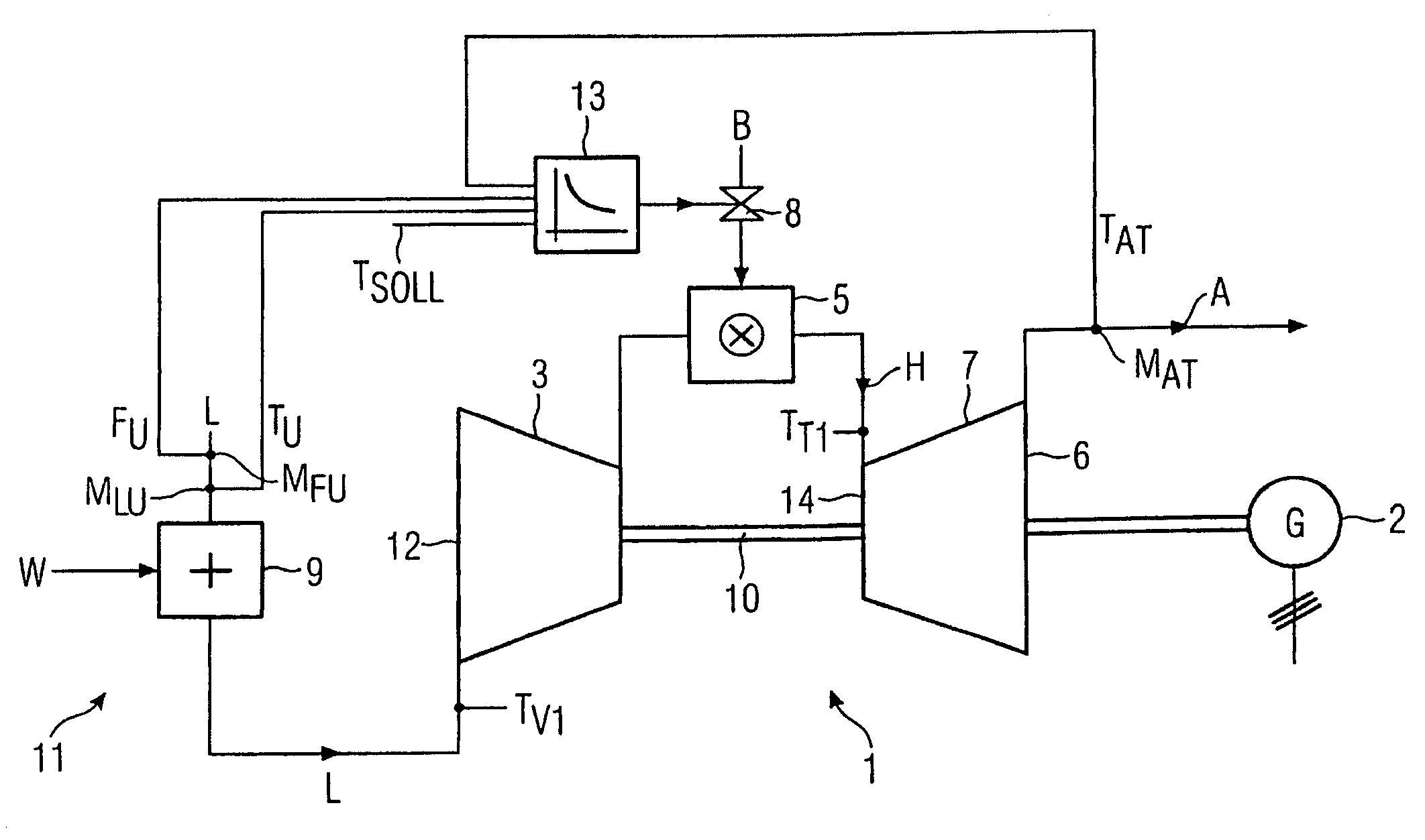
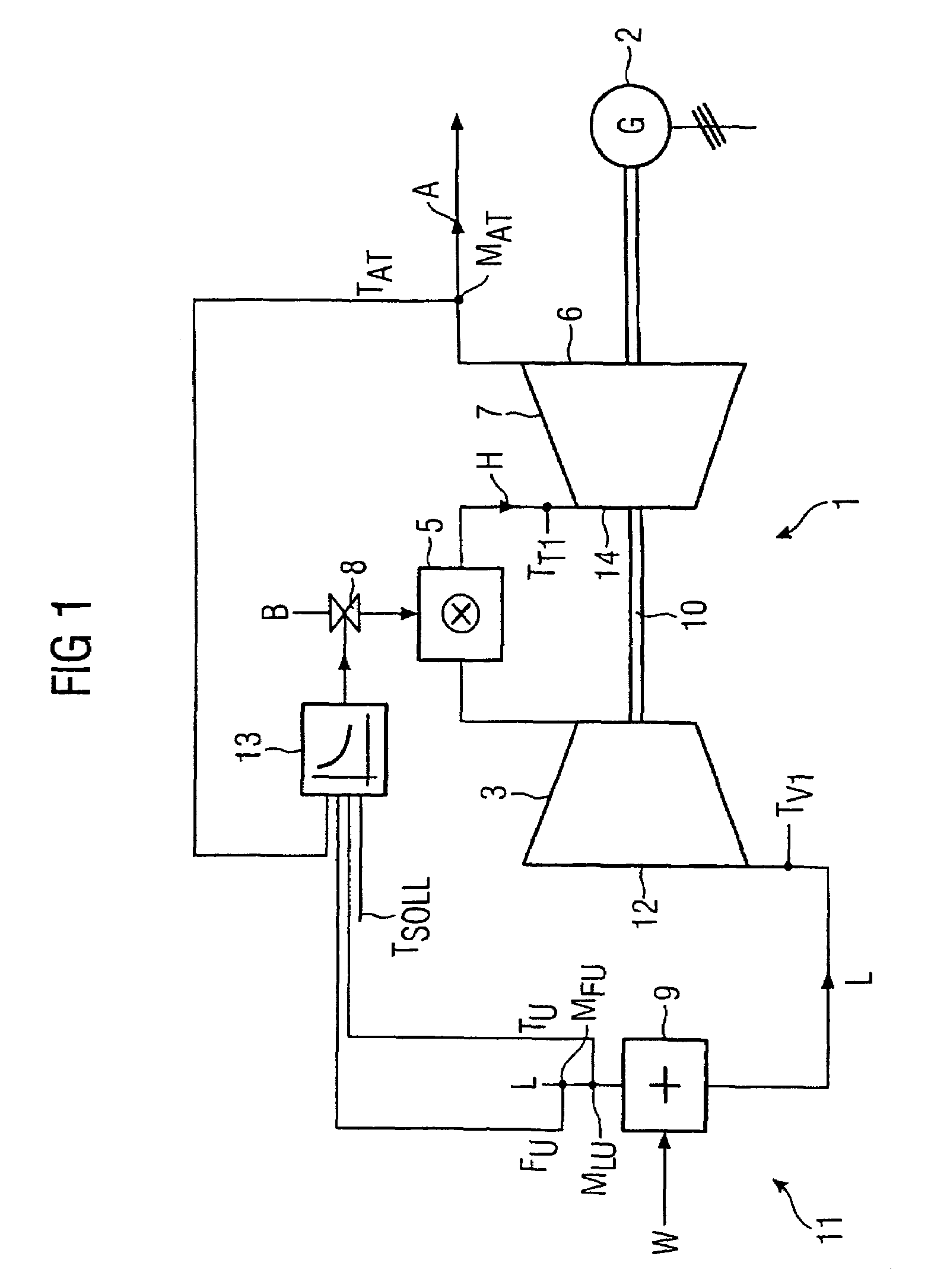
[0027]FIG. 1 diagrammatically depicts a gas turbine installation for converting fossil energy into electrical energy by means of a gas turbine 1 and a generator 2 coupled to it. The stationary gas turbine 1 substantially comprises a compressor 3, a combustion chamber 5 and a turbine part 7. The compressor 3 is connected to the turbine part 7 and the generator 2 via a common rotor shaft10.

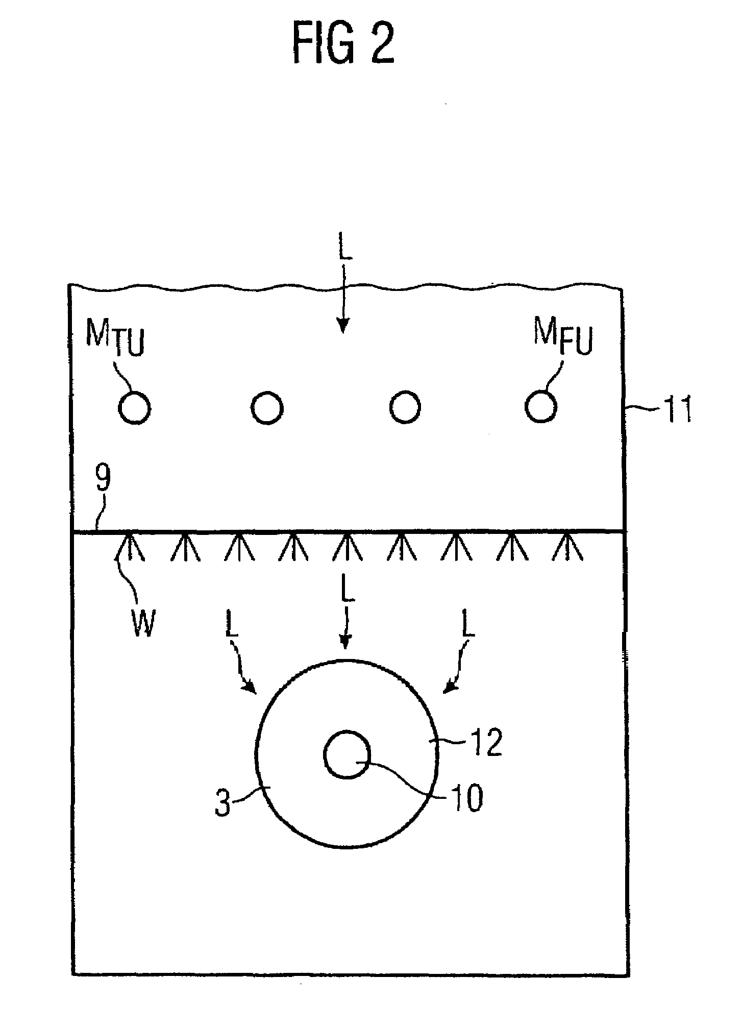
[0028]When the gas turbine 1 is operating, the compressor 3 sucks in air through an intake housing 11 and compresses it. The compressed air is mixed with a fuel B, which can be supplied through a shut-off member 8, in a burner and fed to the combustion chamber 5. In operation, the mixture burns to form a hot gas H which then flows into the turbine part 7, where the hot gas H expands and in so doing drives the rotor shaft 10. Then, the hot gas H leaves the gas turbine 1 as exhaust gas A, passing into an exhaust conduit (not shown in more detail). The rotor shaft 10 drives the compressor 3 and the gen...


PUM


Abstract

The invention relates to a regulation of the temperature of a hot gas of a gas turbine, particularly of a stationary gas turbine used for generating electricity, which comprises an injecting device for injecting a liquid into an airflow, which can be drawn into a compressor and with the aid of which a fuel inside a combustion chamber, which is situated downstream, combusts while producing the hot gas that is subsequently expanded when flowing through the turbine part located downstream. A temperature measuring device is provided that measures the temperature of the airflow before the compressor, whereby the temperature of the hot gas is regulated by the quantity of fuel. The aim of the invention is to provide a regulation with which, during wet compression operation, the serviceable life of the components subjected to the action of hot gas is lengthened. To this end, the invention provides that the temperature measuring device is mounted before the injecting device, and that the temperature of the airflow is calculated at the entry of the compressor by using the measured temperature.

Description

CROSS REFERENCE TO RELATED APPLICATION[0001]This application is the U.S. National Stage of International Application No. PCT / EP2004 / 003184, filed Mar. 25, 2004 and claims the benefit thereof The International Application claims the benefits of German Patent application No. 10314389.0 DE filed Mar. 28, 2003, and European Patent application No. 03022209.5 EP filed Sep. 30, 2003, all of the applications are incorporated by reference herein in their entirety.FIELD OF THE INVENTION[0002]The invention relates to a gas turbine, in particular a stationary gas turbine for power generation, in accordance with the preamble of the claims, and to a temperature-measuring device for recording the temperature of the air stream of a gas turbine in accordance with the preamble of the claims. The invention also relates to a control arrangement for controlling the hot-gas temperature of a gas turbine in accordance with the preamble of the claims.BACKGROUND OF THE INVENTION[0003]It is known that station...

Claims


Application Information

Patent Timeline
Patent Type & Authority Patents(United States)
IPC IPC(8): F02C3/30F02C9/28F02C7/143
CPCF02C7/1435F02C9/28F05D2270/0831F05D2270/303F05D2260/211
Inventor NUDING, JOACHIM-RENELEUSDEN, CHRISTOPH PELSTAPPEN, MARCO
Owner SIEMENS ENERGY GLOBAL GMBH & CO KG
Why Eureka
Try Eureka