
Steerable underreamer/stabilizer assembly and method

a stabilizer and underreamer technology, applied in the direction of drilling pipes, directional drilling, gas removal, etc., can solve the problems of bending the bit, the borehole does not maintain a vertical trajectory along its entire depth, and the borehole deviation can be significan

Inactive Publication Date: 2009-04-07
SMITH INT INC
View PDF44 Cites 87 Cited by
  • Summary
  • Abstract
  • Description
  • Claims
  • Application Information

AI Technical Summary

Benefits of technology

[0020]According to another aspect of the invention, a method to drill a borehole includes disposing a drill bit and a stabilized underreamer at a distal end of a drillstring, positioning a drilling assembly behind the stabilized underreamer, drilling a pilot bore with the drill bit and the drilling assembly, underreaming the pilot bore with underreamer cutters of the stabilized underreamer, and stabilizing the drill bit with stabilizer pads of the stabilized underreamer.

Problems solved by technology

While most drilling operations begin as vertical drilling operations, often the borehole drilled does not maintain a vertical trajectory along its entire depth.
However, over distances of over several thousand feet, borehole deviation can be significant.
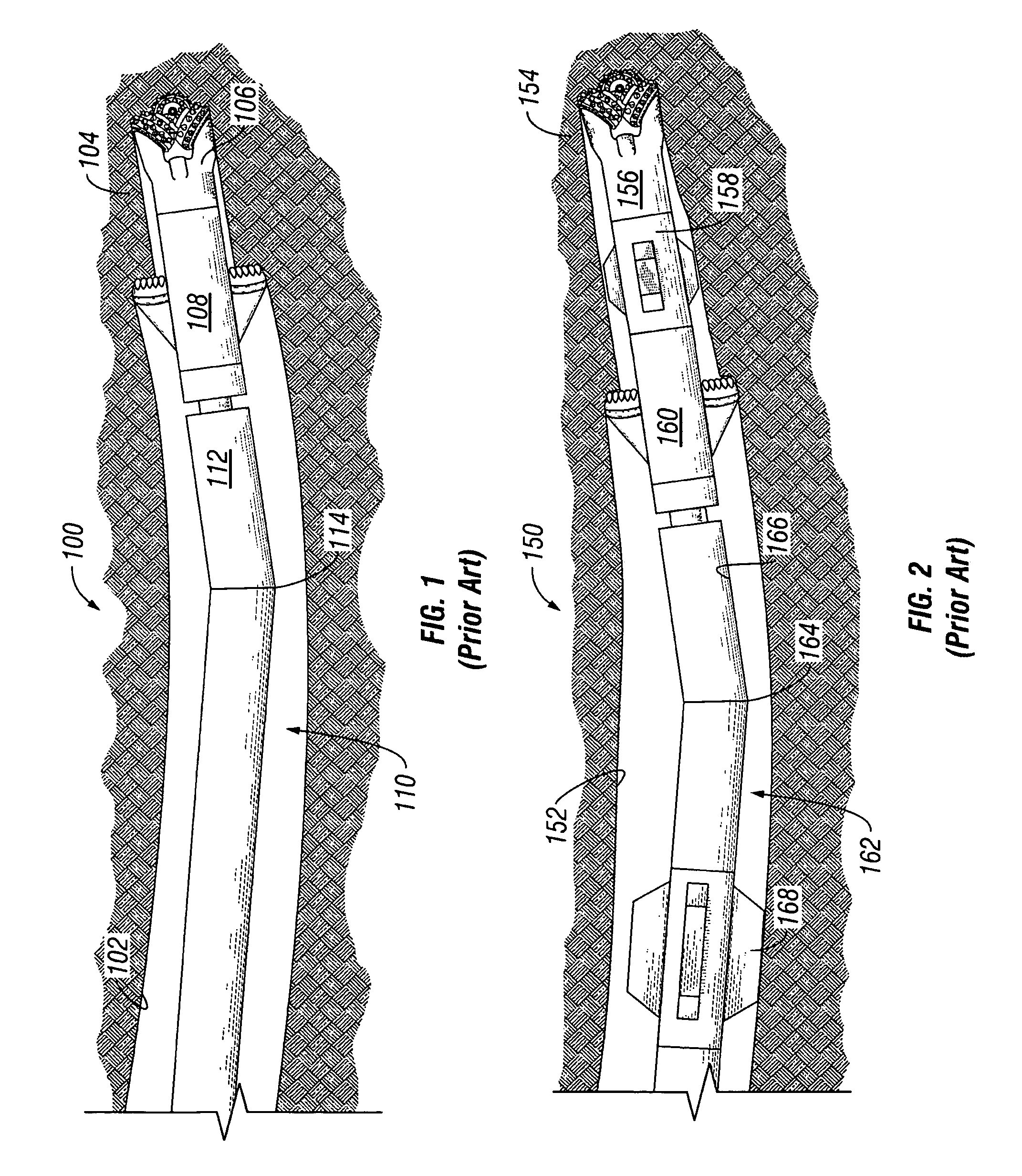
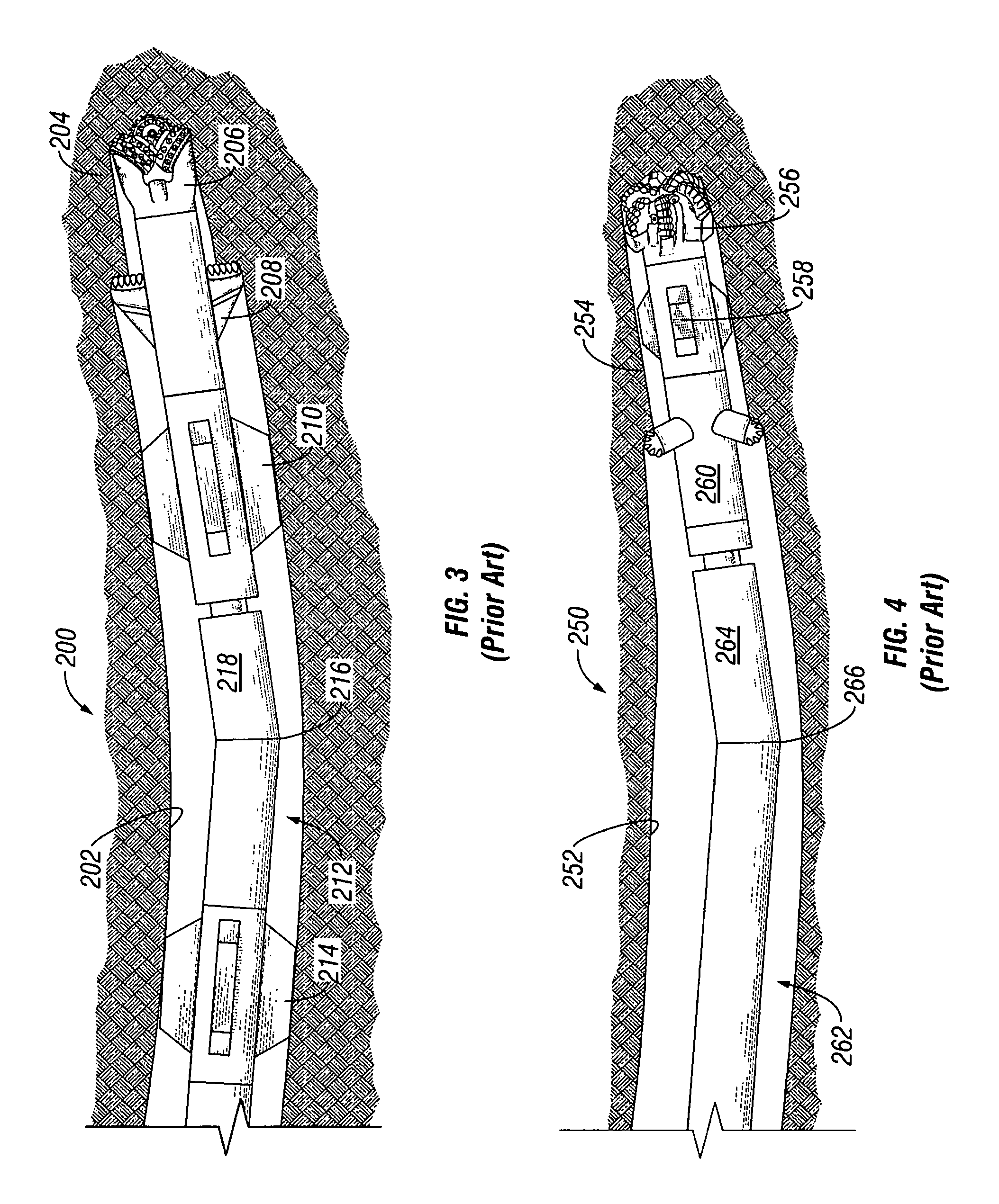
One drawback of directional drilling with a mud motor and a bent housing is that the bend may create high lateral loads on the bit, particularly when the system is either kicking off (that is, initiating a directional change) from straight hole, or when it is being rotated in straight hole.
The high lateral loads can cause excessive bit wear and a rough wellbore wall surface.
Another drawback of directional drilling with a mud motor and a bent housing arises when the drillstring rotation is stopped and forward progress of the BHA continues with the positive displacement mud motor.
During these periods, the drillstring slides further into the borehole as it is drilled and does not enjoy the benefit of rotation to prevent it from sticking in the formation.
Particularly, such operations carry an increased risk that the drillstring will become stuck in the borehole and will require a costly fishing operation to retrieve the drillstring and BHA.
Once the drillstring and BHA is fished out, the apparatus is again run into the borehole where sticking may again become a problem if the borehole is to be deviated again and the drillstring rotation stopped.
Furthermore, another drawback to drilling without rotation is that the effective coefficient of friction is higher, making it more difficult to advance the drillstring into the wellbore.
This results in a lower rate of penetration than when rotating, and can reduce the overall “reach”, or extent to which the wellbore can be drilled horizontally from the drill rig.

Method used


Image

  • Steerable underreamer/stabilizer assembly and method
  • Steerable underreamer/stabilizer assembly and method
  • Steerable underreamer/stabilizer assembly and method

Examples


Embodiment Construction

[0029]Embodiments of the invention relate generally to a drilling assembly to be used in subterranean drilling. More particularly, certain embodiments relate to a bottom hole assembly incorporating a stabilized underreamer located between a drill bit and a directional drilling assembly. in some embodiments, the drilling assembly includes a rotary steerable assembly and in other embodiments, the drilling assembly includes a downhole mud motor. Furthermore, in certain embodiments an expandable stabilizer is positioned above or upon the directional drilling assembly.

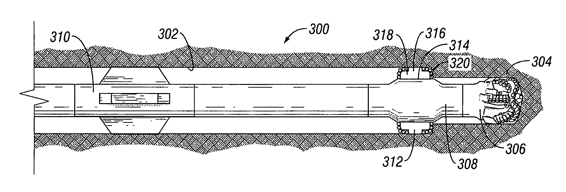
[0030]Referring now to FIG. 5, a bottom hole assembly as disclosed in U.S. Pat. No. 6,732,817 (“the 817 patent”), from which the present application claims benefit and is hereby incorporated by reference herein, is shown. Particularly, a BHA 300 is depicted drilling a borehole 302 in a subterranean formation 304. As such, BHA 300 includes a pilot bit 306, an expandable reamer 308, and an expandable stabilizer 310. Expandabl...


PUM


Abstract

A bottom hole assembly includes a drill bit, a stabilized underreamer assembly located behind the drill bit, and a drilling assembly. A method to drill a formation includes positioning a stabilized underreamer assembly behind a drill bit, positioning a drilling assembly behind the stabilized underreamer assembly, and rotating the drill bit and stabilized underreamer assembly with the drilling assembly. A stabilized underreamer located between a directional drilling assembly and a drill bit includes at least one arm assembly extending from the stabilized underreamer assembly, wherein the arm assembly includes a stabilizer portion and an underreamer cutting structure.

Description

CROSS-REFERENCE TO RELATED APPLICATIONS[0001]The present application is a Continuation-In-Part of U.S. patent application Ser. No. 10 / 841,314 (“the '314 application”), filed on May 7, 2004. As such, the '314 application is a Divisional of U.S. patent application Ser. No. 10 / 078,067, filed on Feb. 19, 2002, now U.S. Pat. No. 6,732,817.BACKGROUND OF INVENTION[0002]Subterranean drilling operations are often performed to locate (exploration) or to retrieve (production) subterranean hydrocarbon deposits. Most of these operations include an offshore or land-based drilling rig to drive a plurality of interconnected drill pipes known as a drillstring. Large motors at the surface of the drilling rig apply torque and rotation to the drillstring, and the weight of the drillstring components provides downward axial force. At the distal end of the drillstring, a collection of drilling equipment known to one of ordinary skill in the art as a bottom hole assembly (“BHA”), is mounted. Typically, th...

Claims


Application Information

Patent Timeline
Patent Type & Authority Patents(United States)
IPC IPC(8): E21B7/04E21B10/26
CPCE21B7/067E21B10/322E21B17/1014E21B7/06E21B7/068E21B10/26E21B10/32E21F7/00
Inventor UNDERWOOD, LANCE D.DEWEY, CHARLES H.
Owner SMITH INT INC
Learn More