Rotor blade tip planform

a technology of rotor blades and planforms, which is applied in the direction of rotocraft, machines/engines, vehicles, etc., can solve the problems of reducing the hovering efficiency of the rotor system, increasing the drag of the tip airfoil, and limited range of mach numbers and angles of incidence, so as to improve the hovering efficiency and improve the lift and drag characteristics , the effect of improving the efficiency

Active Publication Date: 2009-04-07
SIKORSKY AIRCRAFT CORP
View PDF9 Cites 21 Cited by
  • Summary
  • Abstract
  • Description
  • Claims
  • Application Information

AI Technical Summary

Benefits of technology

[0007]A main rotor blade according to the present invention includes a rotor blade that encompasses the use of airfoils with improved lift and drag characteristics at hover critical Mach numbers, along with tip planform designs that improve hover efficiency at lift levels that avoid conflict with a maximum gross weight required for efficient forward flight operation. The applicants have determined that the rate of blade tip chord taper controls the gross weight (thrust) at which hover efficiency improvements occur when hover optimized high lift airfoils are utilized in the blade tip region. The hover lift level at which the hover efficiency gain occurs is tuned to match the rotor forward flight lift capability. Increased tip taper lowers the hover thrust at which the efficiency improvement is seen, and decreased taper increases the corresponding thrust.
[0008]The rotor blade tip planform is utilized in combination with tip sweep and tip anhedral to obtain maximum benefit. Tip sweep matches the tip airfoil Mach number in hover to the Mach number at which airfoil maximum lift is tailored. Anhedral is utilized to reduce induced hover losses and further increase hover efficiency. Increased tip taper reduces anhedral related power penalties in forward flight.
[0009]The present invention therefore provides a rotor blade tip planform which may be used in combination with a hover optimized high lift tip airfoil section so that the resulting combination increases the hover efficiency while not only avoiding conflict with the gross weight of efficient forward flight operations, but rather, helps improve it.

Problems solved by technology

In general, airfoils have a limited range of Mach numbers and angles of incidence with respect to the relative wind over which they operate efficiently.
However, once the tip airfoil maximum lift coefficient is approached at its operating Mach number, the drag of the tip airfoil increases rapidly, and the hovering efficiency of the rotor system accordingly drops.
Because the tip of the hovering rotor blade is operating at the highest Mach number, it will be the first to experience the onset of stall and, therefore, an increase in drag, resulting in a drop off in rotor hovering efficiency.
However, the use of high lift airfoils over the tip region of rotor blades is of minimal use if the rotor blade forward flight performance efficiency becomes resultantly restricted as a consequence of advancing and retreating side airfoil requirements that differ from hover requirements.
While current computer based airfoil design codes are capable of assisting in the development of optimized blade designs, the design of a multitude of airfoils distributed along the rotor blade span that meet the required lift, drag and pitching moment operational and performance criteria in hover and forward flight is very difficult.

Method used


Image

  • Rotor blade tip planform
  • Rotor blade tip planform
  • Rotor blade tip planform

Examples


Embodiment Construction

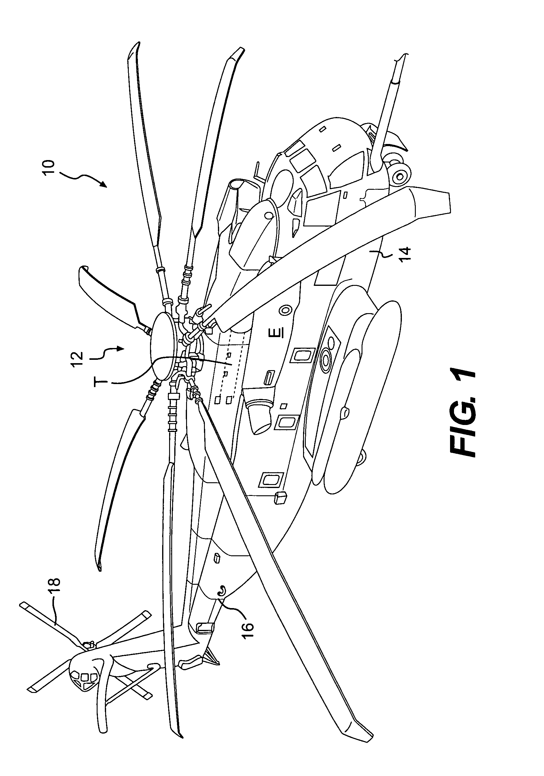
[0018]FIG. 1 schematically illustrates a rotary-wing aircraft 10 having a main rotor assembly 12. The aircraft 10 includes an airframe 14 having an extending tail 16 which mounts an anti-torque rotor 18. The main rotor assembly 12 is driven through a transmission (illustrated schematically at T) by one or more engines E. The present invention may be embodied for use with rotor assemblies of other helicopters, high speed coaxial counter-rotating aircraft with translational thrust systems, turbo-props, tilt-rotor aircraft and other such aircraft. It should be understood that a Sikorsky CH-53 type helicopter configuration as illustrated in the disclosed embodiment is for discussion purposes only.

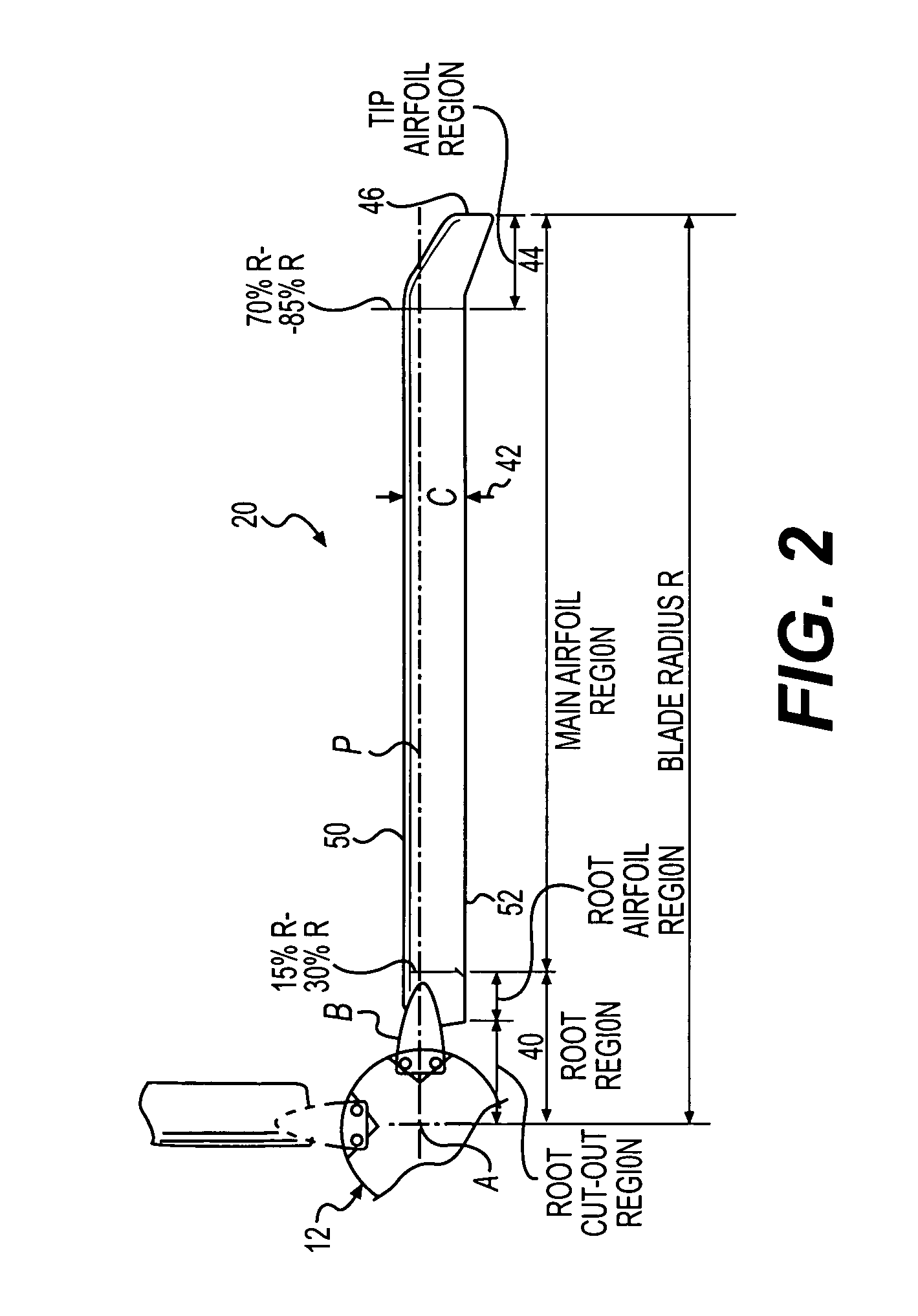
[0019]FIG. 2 illustrates a general exemplary plan view of a main rotor blade 20. The rotor blade 20 can generally be divided into a root region 40, a main region 42, and a tip region 44. The root, main, and tip regions 40, 42, 44 define the span of the rotor blade 20 and define a blade radius R...


PUM


Abstract

A main rotor blade incorporating a rotor blade tip region having a tip chord and a tip taper such that the ratio of the main rotor blade chord to the tip chord is approximately 0.30. The tip taper ratio preferably providing an approximately 28% area of reduction in said outer 10% of said blade span. The tip region preferably further including a hover optimized high lift airfoil and a tip sweep that reaches a constant value of approximately 30 degrees along the quarter chord line.

Description

BACKGROUND OF THE INVENTION[0001]The present application is directed to a main rotor blade tip design for rotary-wing aircraft and more particularly to a main rotor blade tip planform that enhances hover performance by the combined tailoring of blade tip sweep, blade tip taper and blade tip anhedral.[0002]In general, airfoils have a limited range of Mach numbers and angles of incidence with respect to the relative wind over which they operate efficiently. In general, it may be claimed that the efficiency of a hovering rotor will continue to improve as rotor thrust, and simultaneously, airfoil lift continues to increase. However, once the tip airfoil maximum lift coefficient is approached at its operating Mach number, the drag of the tip airfoil increases rapidly, and the hovering efficiency of the rotor system accordingly drops. Typically, an airfoil operating at a higher Mach number will stall sooner than one operating at lower Mach numbers. Because the tip of the hovering rotor bl...

Claims


Application Information

Patent Timeline
Patent Type & Authority Patents(United States)
IPC IPC(8): B64C27/46
CPCB64C27/463
Inventor MOFFITT, ROBERT C.EGOLF, THOMAS ALANBEATTY, ROBERT D.KARPOWICH, JOHN K.BAGAI, ASHISH
Owner SIKORSKY AIRCRAFT CORP
Why Eureka
Try Eureka