
High density disk recording medium and apparatus using the same

a high density disk and recording medium technology, applied in mechanical recording, recording signal processing, instruments, etc., can solve the problems of hd-dvd b>10/b>, hd-dvd b>10/b>, and/or the servo-mechanics would be irreparably damaged, and the objective lens ol will collide with the misplaced,

Inactive Publication Date: 2009-04-07
LG ELECTRONICS INC
View PDF39 Cites 1 Cited by
  • Summary
  • Abstract
  • Description
  • Claims
  • Application Information

AI Technical Summary

Benefits of technology

The present invention provides a high-density disk that prevents the collision of an objective lens and detects misplacement of the disk through a conventional focusing operation even when the disk is placed upside down. The disk has a clamping area with two thicknesses, where the first thickness is greater than the second thickness to ensure proper clamping. The second clamping surface is coplanar with the second surface of the disk and may have a protruding portion. The technical effects of the invention include preventing damage to the disk and ensuring accurate detection of disk misplacement.

Problems solved by technology

However, in this case, the objective lens OL will collide with the misplaced HD-DVD 10.
Consequently, the HD-DVD 10, the objective lens OL, and / or the servo-mechanism would be irreparably damaged.

Method used


Image

  • High density disk recording medium and apparatus using the same
  • High density disk recording medium and apparatus using the same
  • High density disk recording medium and apparatus using the same

Examples


second embodiment

[0041]FIG. 9 is a sectional view of the second preferred embodiment of a high-density disk structured according to the present invention. a high-density disk 21 according to the present invention has a clamping zone structured such that the thickness of each side, P1 and P2, which are created by bisecting the clamping zone with an imaginary longitudinal center plane “c,” are different. Namely, P1 is greater than P2, where both P1 and P2 are both greater than one-half of the whole thickness of the disk 21 as shown in FIG. 9. The side opposite to the recording side protrudes from disk surface a greater distance than of the recording side. As shown in FIG. 9, the height D1, which ranges approximately from 0.1 mm to 0.6 mm, is greater than D2, which is located on the recording side.

[0042]The protruding height D2 of the recording side is preferably determined to be within a range that ensures a successful focus of the pit patterns within the recording layer by the objective lens OL as it...

third embodiment

[0045]FIG. 12 is a sectional view of the third preferred embodiment of a high-density disk structured according to the present invention. a high-density disk 22 according to the present invention has a clamping zone structured such that the thickness of each side, P1 and P2, which are created by bisecting the high-density disk 22 with an imaginary longitudinal center plane “c.” In this case, P1 is greater than P2 and P1 is thicker than one-half of the whole thickness of the disk 22 but P2 is thinner than one-half of the whole thickness of the disk 22. The side opposite to the recording side protrudes from disk surface by the height D1, which ranges from approximately 0.1 mm to 0.6 mm, whereas the clamping zone on the recording side is indented by a height less than D1.

[0046]Therefore, if the high-density disk 22 structured as above is placed normally on the turntable 11, the indented side of the clamping zone, which is in contact with a holder of the turntable 11, allows the recordi...


PUM

PropertyMeasurementUnit
diameteraaaaaaaaaa
diameteraaaaaaaaaa
thicknessaaaaaaaaaa

Abstract

The present invention relates to a high-density disk that is structured to prevent a collision of an optical pickup's objective lens with the high-density disk if the disk is placed upside down in a disk device that is able to record and reproduce signals to / from the high-density disk. A high-density disk recording medium according to the present invention is structured such that, wherein a recording layer having high-density pit patterns is offset from a center plane of disk thickness, both sides of a clamping zone bisected by the center plane have differing thicknesses. One or both sides may protrude from surface of the disk recording medium, or one side of the clamping zone may protrude from the surface while the other side is indented below the surface.

Description

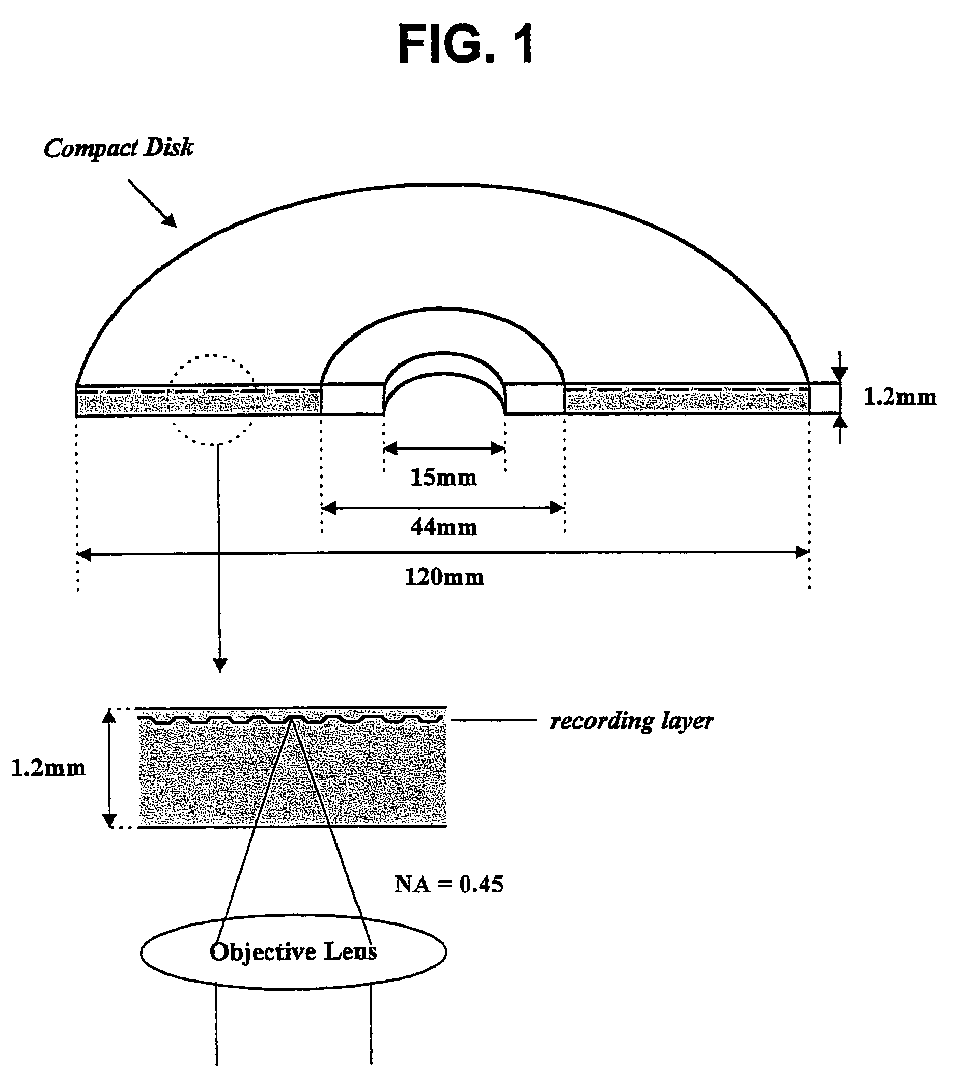
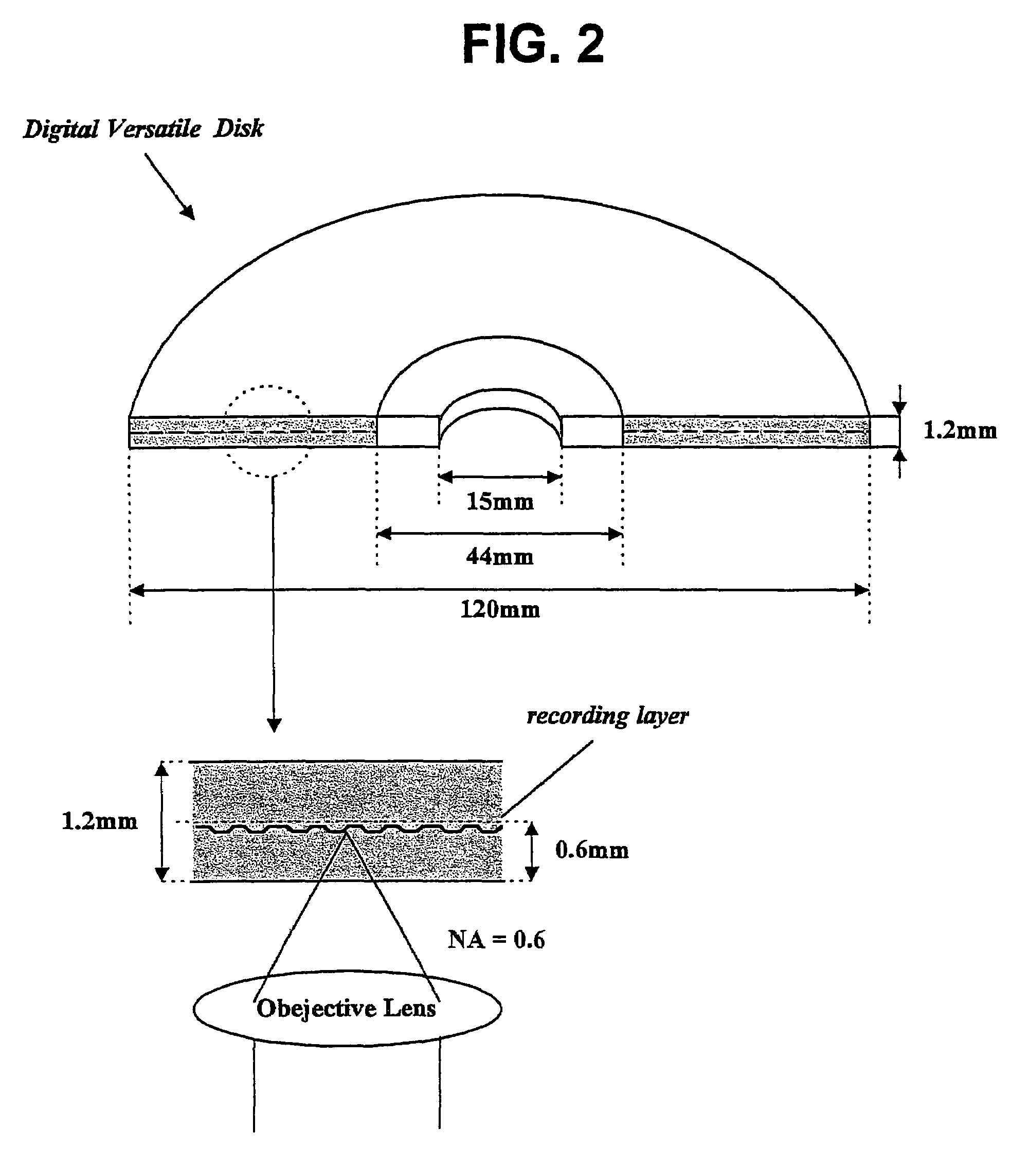
CROSS REFERENCE TO RELATED ART[0001]This application is a division of U.S. application Ser. No. 10 / 097,547, filed Mar. 5, 2002, now U.S. Pat. No. 7,012,880 which claims the benefit of Korean Patent Application No. 2001-26250, filed on May 14, 2001, which is hereby incorporated by reference in its entirety.BACKGROUND OF THE INVENTION[0002]1. Field of the Invention[0003]The present invention relates to a high-density disk structure preventing collision of an optical pickup's objective lens with a high-density disk which is placed upside down in a disk device being able to reproduce and record signals from / to a high-density disk such as a high-density digital versatile disk (called “HD-DVD” hereinafter).[0004]2. Description of the Related Art[0005]A compact disk, usually called “CD,” is 1.2 mm in thickness and 120 mm in diameter as shown in FIG. 1. A CD has a center hole of 15 mm diameter and a clamping zone of 44 mm, which encircles the center hole where the clamping zone is clamped b...

Claims


Application Information

Patent Timeline
Patent Type & Authority Patents(United States)
IPC IPC(8): G11B3/70G11B7/085G11B7/24G11B7/002G11B19/04G11B19/12G11B23/00
CPCG11B7/08511G11B7/24097G11B23/0035G11B7/002
Inventor KIM, JIN YONGPARK, KYUNG CHAN
Owner LG ELECTRONICS INC
Learn More