RFID tag
a radio frequency identification and tag technology, applied in the field of rfid (radio frequency identification) tags, can solve the problem of insufficient elimination effect of illegal use, and achieve the effect of higher radiation and receiving characteristics of antennas and higher
- Summary
- Abstract
- Description
- Claims
- Application Information
AI Technical Summary
Benefits of technology
Problems solved by technology
Method used
Image
Examples
first embodiment
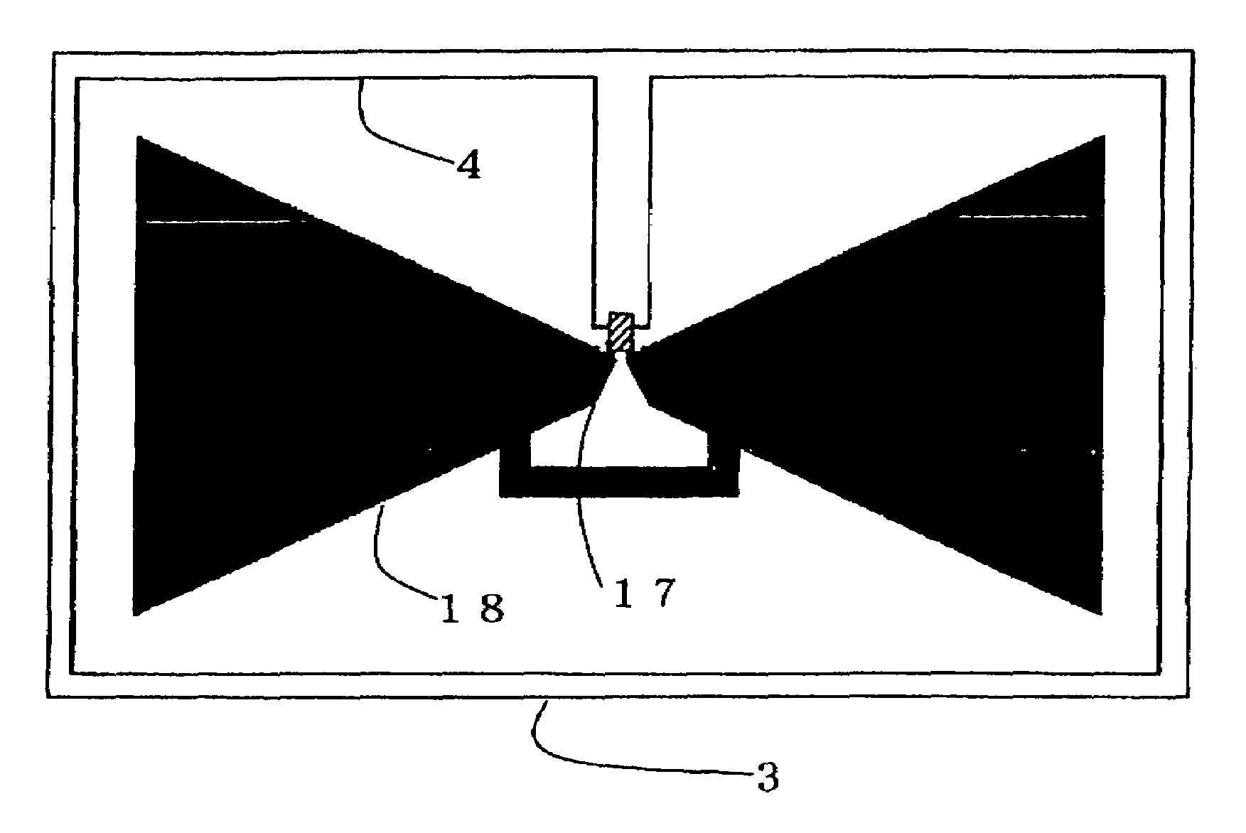
[0045]FIG. 4 illustrates a structure of the RFID tag of the present invention. In this RFID tag, the operating frequency is assumed as about 950 MHz but another frequency may also be selected. The size of this RFID tag is set to 120 mm×60 mm.
[0046]In the RFID tag, an antenna 18 is formed on a film sheet 3 and a detecting block 4 is formed in the circumference of the antenna 18.
[0047]Moreover, an IC chip 17 is arranged in the manner as bridging over the antenna 18 and a detecting block 4. The film sheet is formed of a dielectric material substrate such as FR-4 and so or PET (abbreviation of Polyethylene Telephthalate). The detecting block 4 is formed of a single loop in a length of about 29 cm. The RF tag forms a loop as the detecting block 4 in the circumference of the antenna 18 on the film sheet 3 as illustrated in FIG. 4. Moreover, the antenna 18 and IC chip 17 and so on are covered with a cover sheet (not illustrated). Actually, the RF tag is bonded to an item at the film sheet ...
second embodiment
[0057]Next, FIG. 7 illustrates the antenna impedance (A) when the detecting block of the RF tag in the present invention exists and the antenna impedance (B) when the detecting block does not exist. FIG. 7 illustrates the antenna impedances plotted on a Smith chart.
[0058]FIG. 7(A) illustrates the impedance when the detecting block 41 of FIG. 6 exists. In this case, the antenna impedance is assumed as Z2. In this RF tag, the impedance Z of IC chip 17 in FIG. 6 becomes equal to 36−j245[Ω]. The antenna impedance Z2 becomes equal to 47+j269 Ω. When Z2 is normalized to 50 Ω, Z2=47 / 50+j269 / 50=0.94+j5.38 Ω is obtained. When Z is normalized to 50 Ω, Z=36−j245=0.72−j4.9 Ω is obtained. The normalized impedances Z, Z2 are plotted on the Smith chart as illustrated in FIG. 7(A). The operating frequency is set to about 950 MHz. The Smith chart FIG. 7(A) shows that Z and Z2 are almost in a conjugate relationship and these are almost matched.
[0059]FIG. 7(B) can be obtained by plotting the antenna i...
third embodiment
[0063]FIG. 9 illustrates a radiation spectrum of the antenna showing the RF tag in the present invention. [a.u.] used here is used as a relative unit and is an abbreviation of arbitrary unit. In FIG. 9, field intensity E [a.u.] is plotted on the vertical axis, while frequency is plotted on the horizontal axis. FIG. 9 shows the curve when the detecting block is not provided, namely the double-loop is not provided and the curve when the detecting block 7 is provided, namely the double-loop is provided. In the case where the double-loop is provided (the loops where single-line loop is respectively provided in the internal side and external side), a resonance point (1) of the loop can be found. Moreover, the maximum radiation of the antenna in the RF tag can be found as (2). If the loop length of the detecting block 7 is set to an integer multiple of the half wavelength, the resonance point (1) of the loop will happen to be matched with the maximum radiation (2).
[0064]However, such an e...
PUM
 Abstract
Description
Claims
Application Information
 - R&D
- Intellectual Property
- Life Sciences
- Materials
- Tech Scout
- Unparalleled Data Quality
- Higher Quality Content
- 60% Fewer Hallucinations
Browse by: Latest US Patents, China's latest patents, Technical Efficacy Thesaurus, Application Domain, Technology Topic, Popular Technical Reports.
© 2025 PatSnap. All rights reserved.Legal|Privacy policy|Modern Slavery Act Transparency Statement|Sitemap|About US| Contact US: help@patsnap.com


