All-plastic optical mini-connector

a mini-connector and all-plastic technology, applied in the direction of optics, instruments, optical light guides, etc., can solve the problems of affecting the optical transmission quality of the bundle, and affecting the optical transmission quality. , to achieve the effect of uniform light distribution across the interface between the ends of the optical fiber bundle, and ensuring the optical transmission quality

Inactive Publication Date: 2009-04-14
THE BOEING CO
View PDF11 Cites 10 Cited by
  • Summary
  • Abstract
  • Description
  • Claims
  • Application Information

AI Technical Summary

Benefits of technology

[0004]In accordance with the present invention, an optical fiber connector includes a first connector insert for holding exposed ends of a bundle of optical fibers of a specified number packed in a pre-determined packing pattern, a second connector insert for similarly holding exposed ends of an opposite bundle of optical fibers of the specified number packed in the pre-determined packing pattern, and a center connector component having opposite first and second ends into which the first and second connector inserts are respectively inserted, and fasteners provided with the first and second ends for securely holding the first and second connector inserts in abutting contact with an optical core element in the center connector component substantially in alignment with each other in order to obtain a high level of optical transmission and uniform light distribution across the interface between the connected bundles of optical fibers.

Problems solved by technology

Conventional connectors typically are made of metal and consequently are bulky, heavy and costly.
Existing applications may require drilling holes through the connector structures for retaining or anchoring them that may result in making them more susceptible to corrosion compromising the strength of the base structure.
Another problem with existing types of connectors that are commonly available is they do not provide a high level of optical transmission or a uniform light distribution across the interface between the ends of the optical fiber bundles.

Method used


Image

  • All-plastic optical mini-connector
  • All-plastic optical mini-connector
  • All-plastic optical mini-connector

Examples


Embodiment Construction

[0011]In the following detailed description, certain preferred embodiments are described as illustrations of the invention in a specific application or physical environment in order to provide a thorough understanding of the present invention. Those methods, procedures, components, or functions which are commonly known to persons of ordinary skill in the relevant art are not described in detail as not to unnecessarily obscure a concise description thereof. Certain specific embodiments or examples are given for purposes of illustration only, and it will be recognized by one skilled in the art that the present invention may be practiced in other analogous applications or environments and / or with other analogous or equivalent variations of the illustrative embodiments.

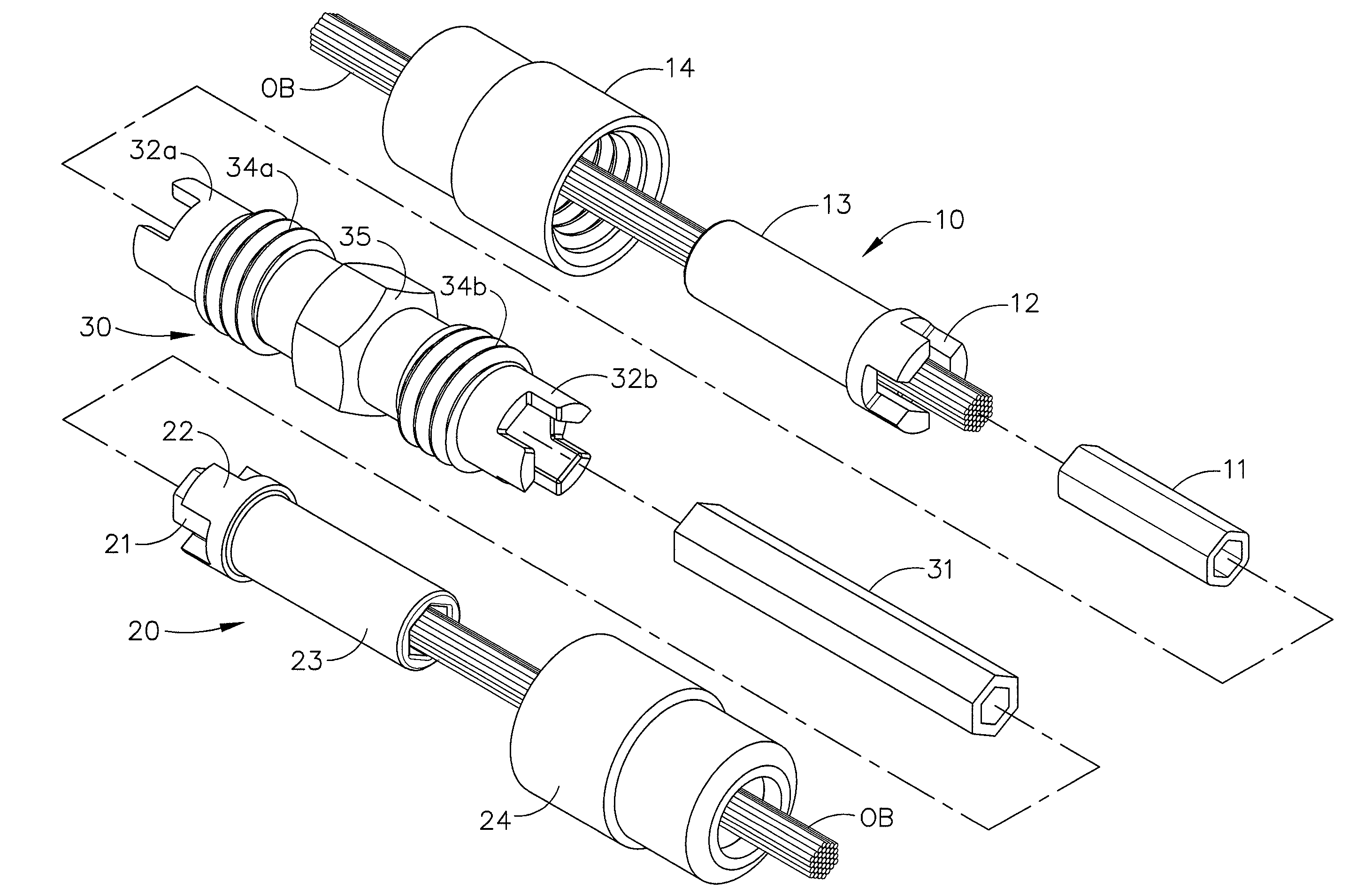
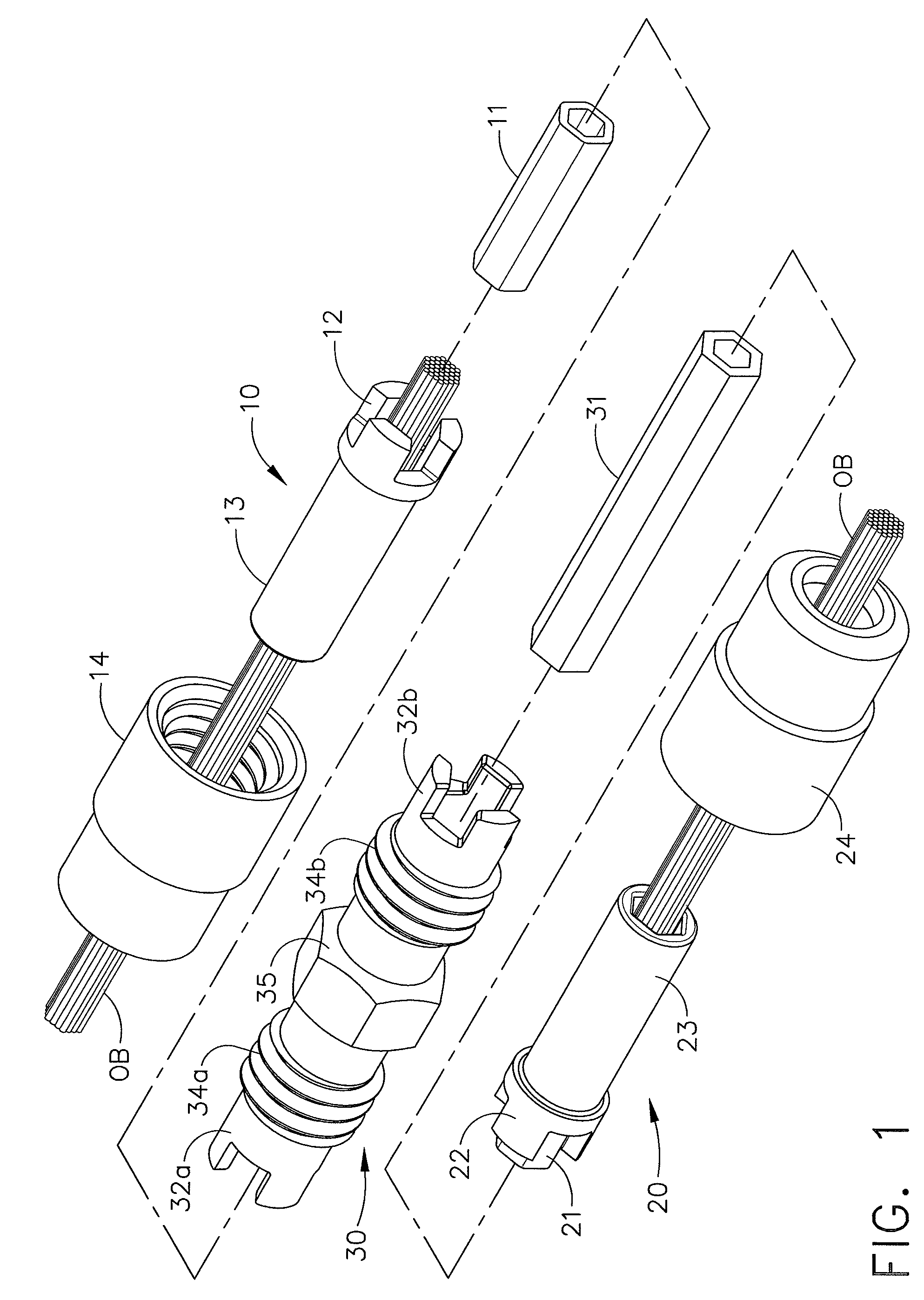
[0012]Referring to FIG. 1, an embodiment of an optical fiber connector is shown having a three component design of a first connector insert 10 for holding exposed ends of a bundle of optical fibers OB of a specified numbe...


PUM


Abstract

An optical fiber connector has a center component provided with opposite first and second ends into which first and second connector inserts holding ends of respective optical fiber bundles are to be inserted, an optical core element mounted in the center component having opposite ends against which the ends of the respective optical fiber bundles in the first and second connector inserts are to be abutted in alignment, and fastener elements provided with the first and second ends for securely holding the first and second connector inserts in abutting contact with the respective opposite ends of the optical core element.

Description

TECHNICAL FIELD[0001]The invention generally relates to a connector for optical fibers for light transmission, and particularly to one having an all-plastic optical fiber connector that provides for high levels of light transmissivity to the output fibers.BACKGROUND[0002]Optical fibers are commonly used to transfer light over given spans to provide illumination and for other light transmission applications. Small-diameter fibers of standard fabrication size are bundled in an array of fibers to deliver the desired optical output, and connectors for the bundled fiber arrays are required when the run of fibers has to span different sections or pieces of equipment. Conventional connectors typically are made of metal and consequently are bulky, heavy and costly. These typical connections also require extreme care to align each end of the mating fibers for efficient coupling of light across the connection. Existing applications may require drilling holes through the connector structures f...

Claims


Application Information

Patent Timeline
Patent Type & Authority Patents(United States)
IPC IPC(8): G02B6/38G02B6/40
CPCG02B6/403G02B6/2808
Inventor MCNIECE, MICHAEL R.ALEXANDER, JOHN V.NOWAK, ROBERT A.BOMBER, RICKMELQUIST, JAMES L.
Owner THE BOEING CO
Why Eureka
Try Eureka