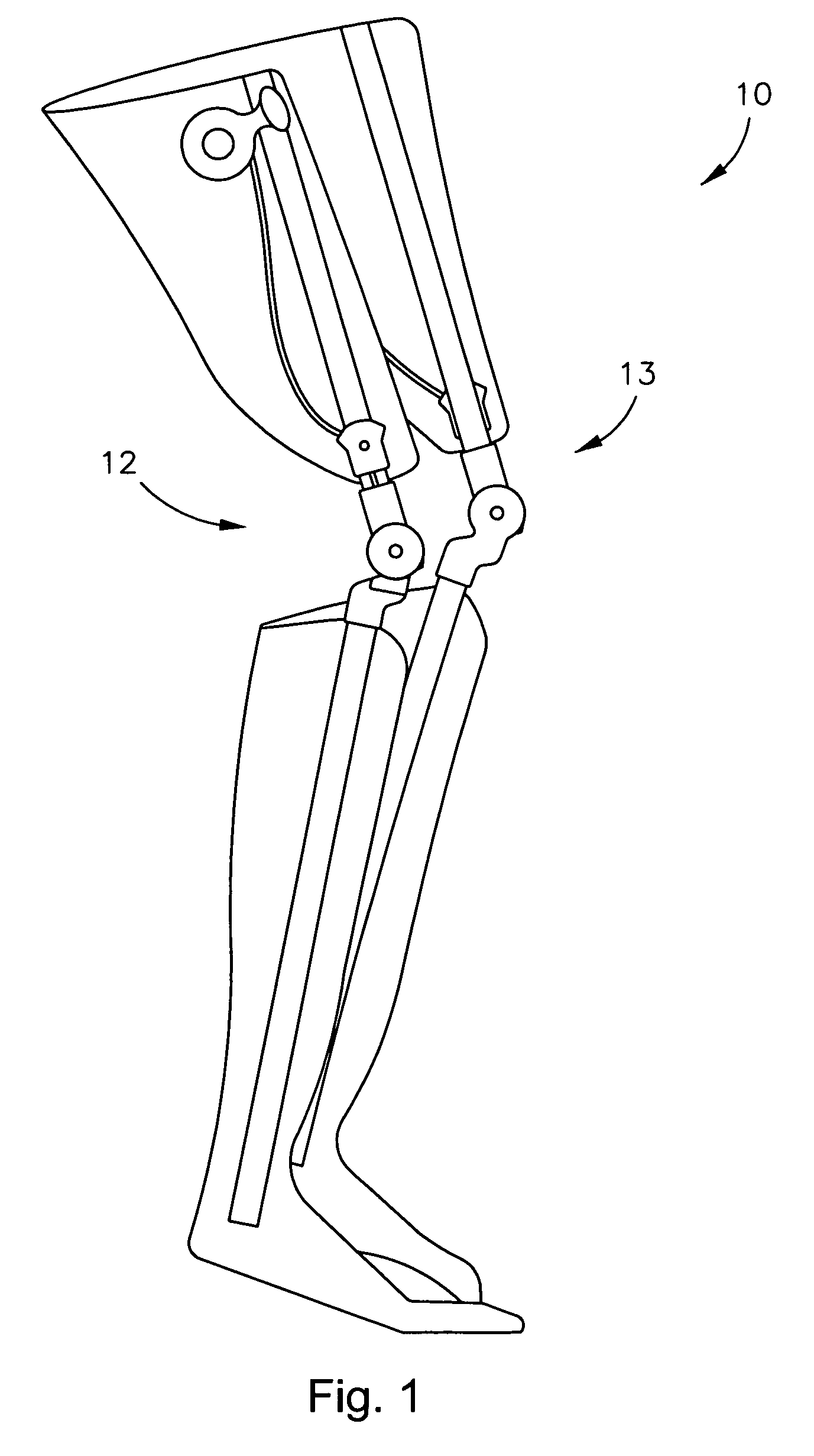
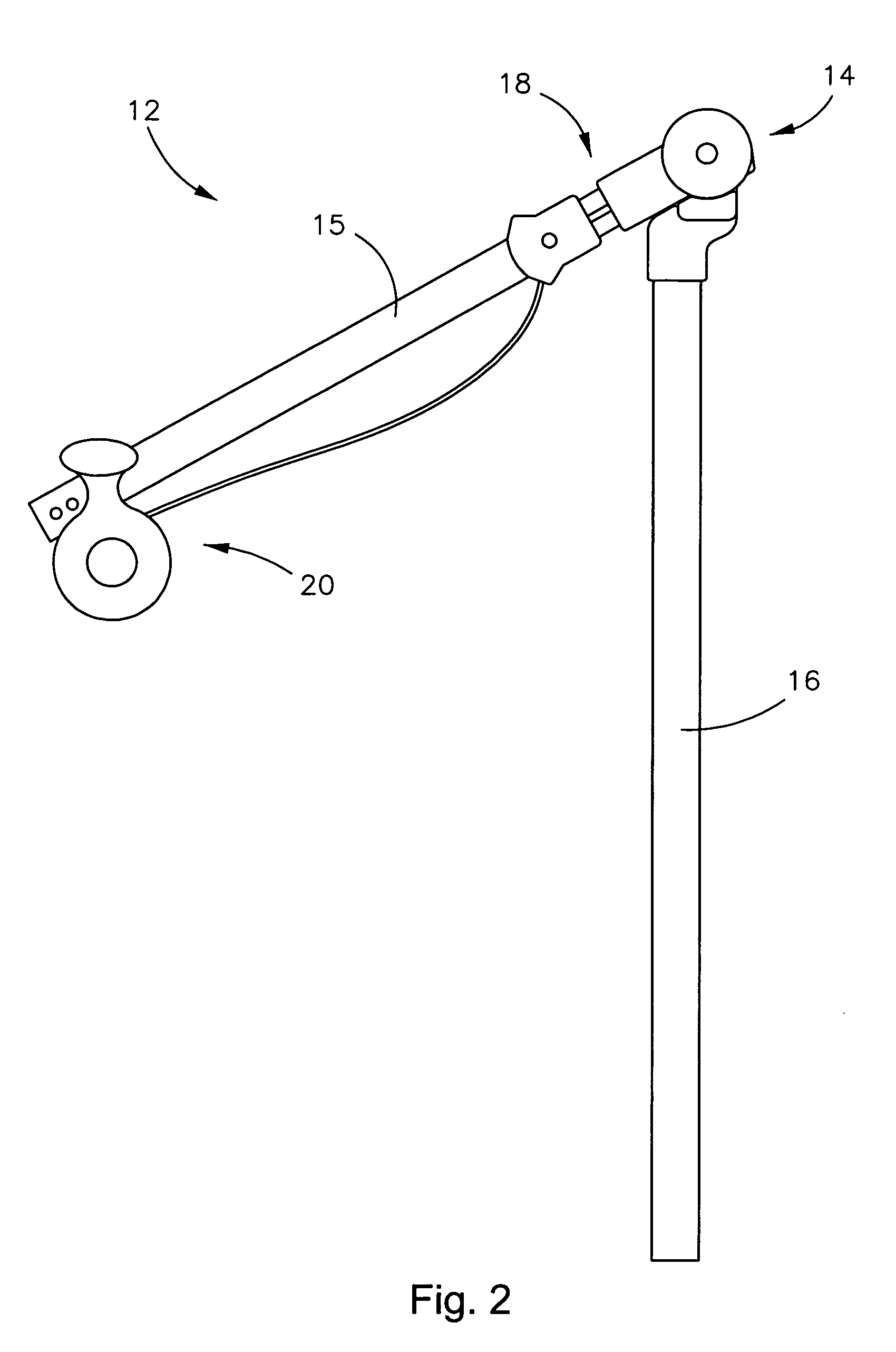
[0007]The present invention provides an orthotic, prosthetic, or rehabilitative device that assists, or takes the place of, muscles that are weak or absent, and that normally control and prevent the knee from lagging during swing-through extension, from buckling at
heel strike through terminal stance on the balls and toes of the foot, and from buckling during sit-to-stand from a chair. The device of the present invention provides controlled, multi-position rotational motion in the extension direction to prevent knee buckling from sit-to-stand through a ratcheting, step-advance feature. Further, resistance to
knee flexion is provided through an elastomeric spring, enabling a dampening shock absorption feature, the elastomeric spring also assisting knee movement from a flexed attitude during the swing-phase to a straight leg position (extension) just prior to initial contact with the floor (
heel strike). Elastomeric material characteristics further enable relatively high stance control moments to be effectively dampened, while swing return moments and rate of return (or
hysteresis) are far less in magnitude and velocity, thereby mimicking normal muscle function.
[0008]The present invention provides a
weight bearing strut assembly capable of supporting the human frame in the act of walking, while enabling a leg to which it is attached to bend in a normal and natural
ambulatory manner. While walking, the present invention provides shock absorption during
heel strike and an accelerating or urging capability to a forward moving lower leg during swing from
knee flexion to extension in preparation for receiving weight upon
heel strike. Both the dampening, shock absorption function and the urging capability or force is adjustable, with a degree of force and
angle of rotation upon which the force is provided being adaptable to suit individual needs. The present invention incorporates the normal and natural
ambulatory motion with the security of a step-advance feature, ensuring support of the knee during
weight bearing extension (e.g., rising from a sitting position). The elastomeric spring can be adapted to reproduce the force deflection curve of any bodily muscle, by varying the size, shape, and / or characteristics of the elastomeric spring.
[0013]In another aspect of the present invention, the hinge assembly is again adapted for an orthotic, prosthetic, or rehabilitative device, and includes a proximal member movably connected to a distal member to allow
angular displacement of the proximal member relative to the distal member between extension and flexion positions, and a disk and a lock slide communicating with the proximal and the distal members, the lock slide and the disk adapted for engagement to one another. In this aspect, engagement of the lock slide with the disk over a first predetermined range arrests
angular displacement of the proximal member relative to the distal member in a direction toward flexion, and provides one-way, ratcheting step-advance in a direction toward extension. Further, angularly displacing the disk relative to the proximal and the distal members over a second pre-determined range provides free
angular displacement of the proximal member relative to the distal member in a direction toward flexion and toward extension, the free angular displacement occurring over the second pre-determined range even if the lock slide is positioned for engagement of the disk.
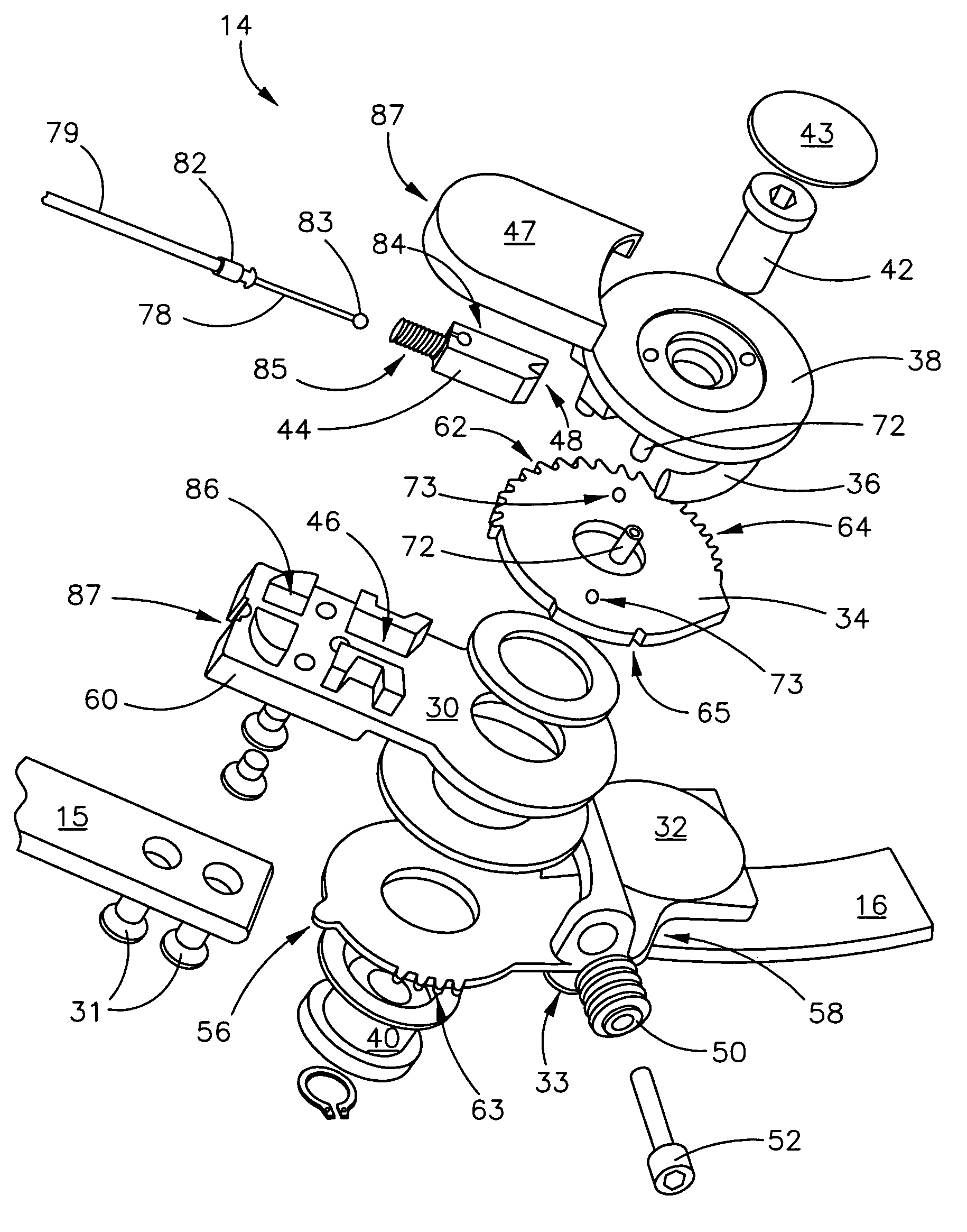
[0018]In another aspect of the present invention, an orthotic, prosthetic, or rehabilitative device is presented and includes a proximal member rotatably connected to a distal member by a hinge assembly, the hinge assembly allowing angular displacement of the proximal member relative to the distal member to and from extension and flexion positions. In this aspect, the hinge assembly includes a disk, a lock slide adapted for engaging the disk, where engagement of the lock slide with the disk, over a first pre-determined range, arrests angular displacement of the proximal member relative to the distal member in a direction toward flexion, and provides one-way, ratcheting step-advance in a direction toward extension. The hinge assembly of this aspect further includes at least one spring communicating with the proximal and the distal members, over a second pre-determined range, to provide a dampening of angular displacement of the proximal member relative to the distal member in a direction toward flexion, and to provide an urging of angular displacement in a direction toward extension. The at least one spring could be a
torsion spring or an elastomeric spring.
[0019]In this aspect, the hinge assembly could also include a mechanism having a catch, the mechanism angularly communicating with the disk and the proximal and the distal members, where engagement of the lock slide within the catch facilitates the dampening of angular displacement in a direction toward flexion and the urging of angular displacement in a direction toward extension. The mechanism could be a spring housing, the spring housing having a channel to keep each spring, each spring compressing against walls of the channel to dampen the angular displacement in a direction toward flexion and decompressing from walls of the channel to urge the angular displacement in a direction toward extension. Further, at least one post could be fixedly connected to the disk and could extend perpendicularly from a face thereof, each post extending into a respective channel of the spring housing, where each post forcibly bears against a respective spring to compress the spring against the walls of the channel and against the face of the disk to dampen the angular displacement in a direction toward flexion, the spring decompressing against and forcibly moving each post to urge the angular displacement in a direction toward extension.
Angular displacement of the spring housing could track, and be tracked by, angular displacement of one of the proximal or the distal members.
[0020]In this aspect, as an alternative to the mechanism having a catch, the hinge assembly could include a rotor having at least one end tooth, the rotor angularly communicating with the disk and the proximal and the distal members, where engagement of the lock slide with the at least one end tooth facilitates the dampening of angular displacement in a direction toward flexion and the urging of angular displacement in a direction toward extension. In this aspect having a rotor, the hinge assembly could further include a spring housing having a channel to keep each spring, each spring compressing against walls of the channel to dampen the angular displacement in a direction toward flexion and decompressing from the walls of the channel to urge the angular displacement in a direction toward extension. In this aspect having a rotor, angular displacement of the rotor could cause the rotor to bear against each spring to forcibly compress each spring against the walls of the channel.


