Supercharge Your Innovation With Domain-Expert AI Agents!

Antenna arrays and methods of making the same

a technology of antenna arrays and antenna arrays, applied in the field of antenna arrays, can solve the problems of complex power feed network, difficult to achieve phase and amplitude correct to get maximum gain on azimuth, and complex power feed network associated with antenna arrays

Inactive Publication Date: 2009-04-14
LAIRD CONNECTIVITY INC
View PDF6 Cites 7 Cited by
  • Summary
  • Abstract
  • Description
  • Claims
  • Application Information

AI Technical Summary

Benefits of technology

"The present invention provides an omni-directional planar array antenna that has wide elements and narrow elements aligned over each other. The antenna has a terminating element that shorts the first and second conductors. It also has a feed element with a transmission line, impedance matching element, and ground plane. The technical effect of this invention is to provide an improved omni-directional planar array antenna that has better performance and reliability."

Problems solved by technology

The power feed network associated with antenna arrays, however, is often complex.
This type of power feed network is complex because antenna pattern and gain depend on physical and network parameters making it very difficult to achieve correct phase and amplitude to get maximum gain on azimuth and minimize side lobes.
Moreover, array antennas of this type are frequently not readily scalable, are difficult to manufacture, are fragile, and are limited in performance by the accumulation of manufacturing errors in the individual components.

Method used


Image

  • Antenna arrays and methods of making the same
  • Antenna arrays and methods of making the same
  • Antenna arrays and methods of making the same

Examples


Embodiment Construction

[0020]FIGS. 1 and 2 and the following paragraphs describe some embodiments of the present invention. Like reference characters are used wherever possible to identify like components or blocks to simplify the description of the various subcomponents described herein. More particularly, the present invention is described in relation to a co-linear coaxial antenna, however, one of ordinary skill in the art will understand other antenna arrays are possible without departing from the spirit and scope of the present invention.

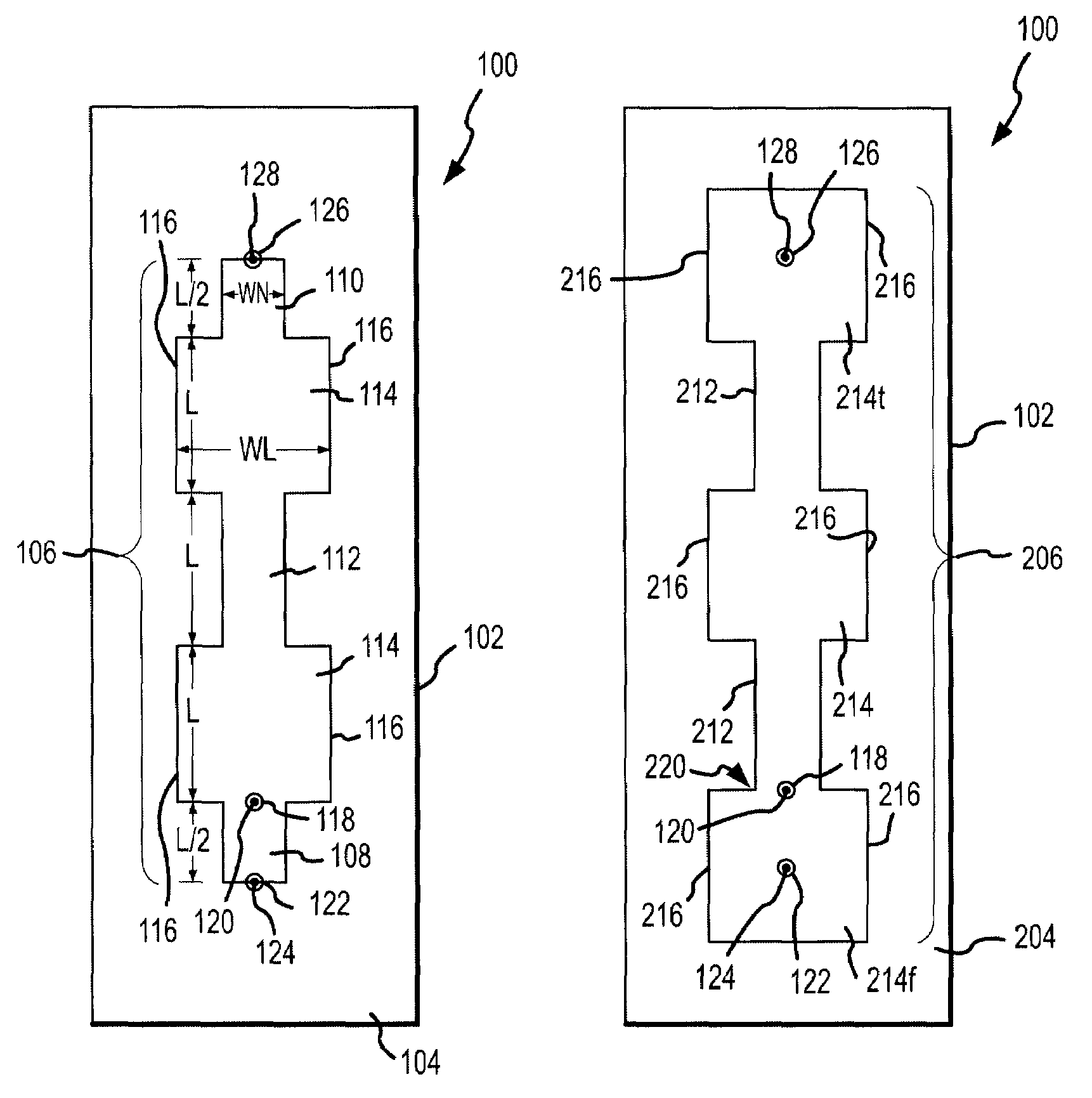
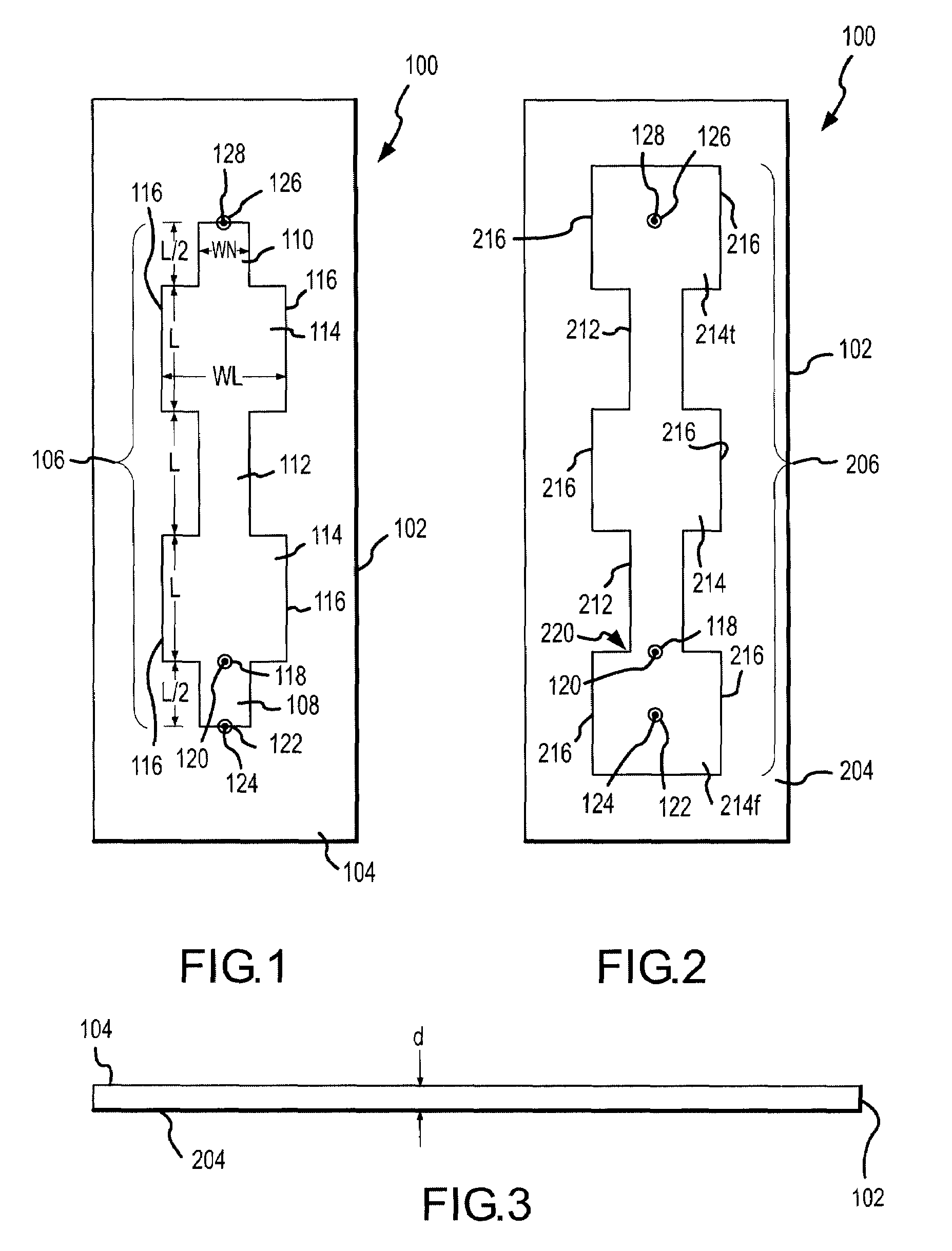
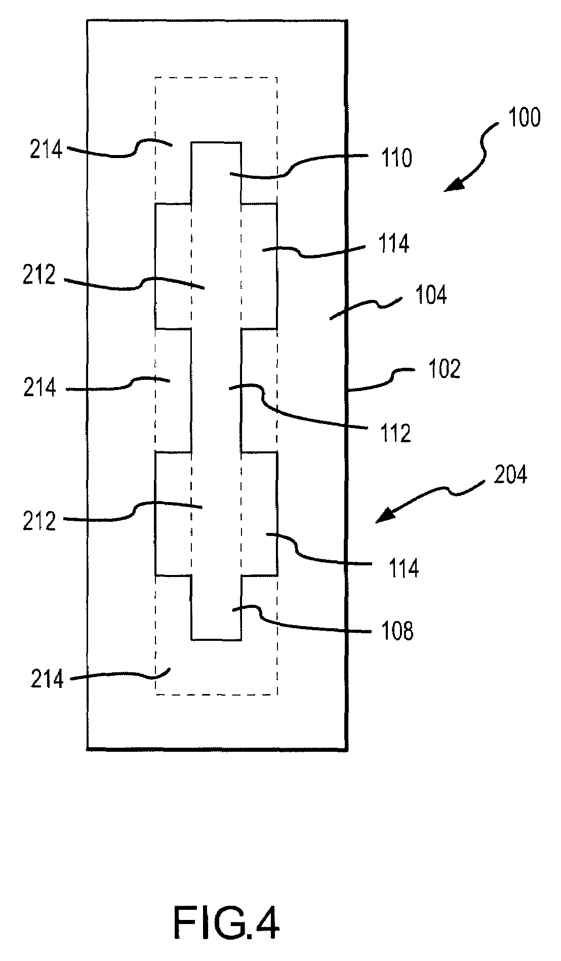
[0021]Referring to FIGS. 1 and 2, an omni-directional linear array antenna 100 exemplary of the present invention is shown. FIG. 1 shows a top side plan view of antenna 100. FIG. 2 shows a bottom side plan view of antenna 100.

[0022]Referring first to FIG. 1, a substrate 102 is shown. While shown as having a generally rectangular shape, substrate 102 does not need to be rectangular, but could be other shapes as desired, such as a random shape, a square shape, a circul...


PUM


Abstract

An omni direction antenna comprising a substrate having a first side and a second side with a first conductor coupled to the first side of the substrate and a second conductor coupled to the second side of the substrate is provided. The first and second conductors comprise wide elements substantially aligned over narrow elements. The antenna further has a terminating element shorting the first and second conductors. A feed element is coupled to the first side wide element, the feed element comprising at least one transmission line, at least one impedance matching element, and at least one ground plane substantially aligned with the at least one transmission line.

Description

[0001]This application is a continuation-in-part of co-pending U.S. patent application Ser. No. 10 / 817,353, filed Apr. 2, 2004, titled ANTENNA ARRAYS AND METHODS OF MAKING THE SAME, incorporated herein by reference as if set out in full, which claims the benefit of U.S. Provisional Application Ser. No. 60 / 461,689, filed Apr. 8, 2003, titled ANTENNA ARRAYS AND METHODS OF MAKING THE SAME.FIELD OF THE INVENTION[0002]The present invention relates to antenna arrays and, more particularly, to omni-directional antenna arrays.BACKGROUND OF THE INVENTION[0003]Radio frequency antennas are often designed as arrays to provide sufficient gain. Types of omni-directional antennas include series fed arrays, co-linear coaxial (COCO) antenna, and the like. The power feed network associated with antenna arrays, however, is often complex. For example, linear arrays typically use a distributed feed network / power divider for the power feed. This type of power feed network is complex because antenna patte...

Claims


Application Information

Patent Timeline
Patent Type & Authority Patents(United States)
IPC IPC(8): H01Q1/38H01Q13/20H01Q21/10
CPCH01Q1/38H01Q13/206H01Q21/10H01Q21/061
Inventor BATEMAN, BLAINE REXELBANCROFT, RANDY
Owner LAIRD CONNECTIVITY INC
Features
  • R&D
  • Intellectual Property
  • Life Sciences
  • Materials
  • Tech Scout
  • Unparalleled Data Quality
  • Higher Quality Content
  • 60% Fewer Hallucinations
Learn More