
Distribution switchgear
a technology of distribution switch and switch body, which is applied in the direction of substations, substations, non-enclosed substations, etc., can solve the problems of unsatisfactory user experience, and achieve the effects of saving maintenance labor, widening the protection range, and increasing reliability
- Summary
- Abstract
- Description
- Claims
- Application Information
AI Technical Summary
Benefits of technology
Problems solved by technology
Method used
Image

Examples
first embodiment
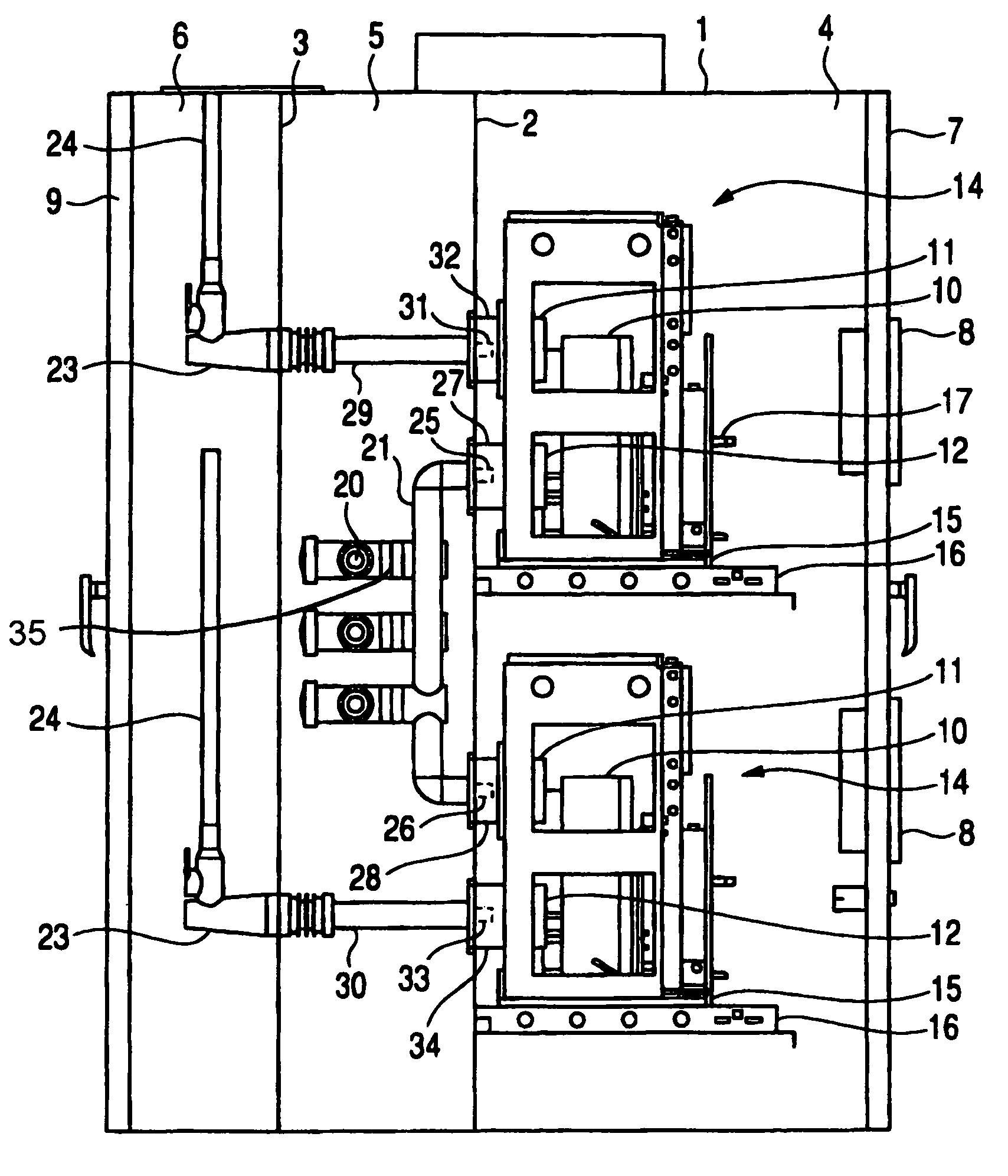
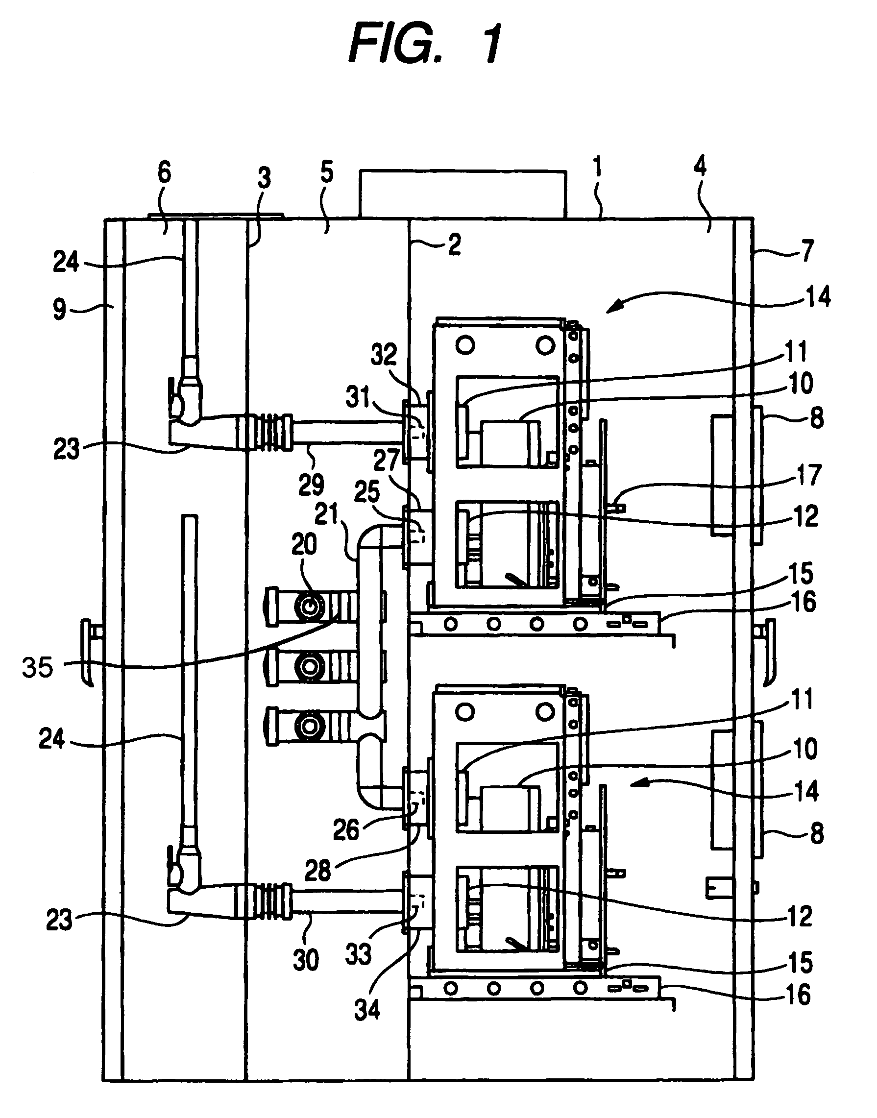
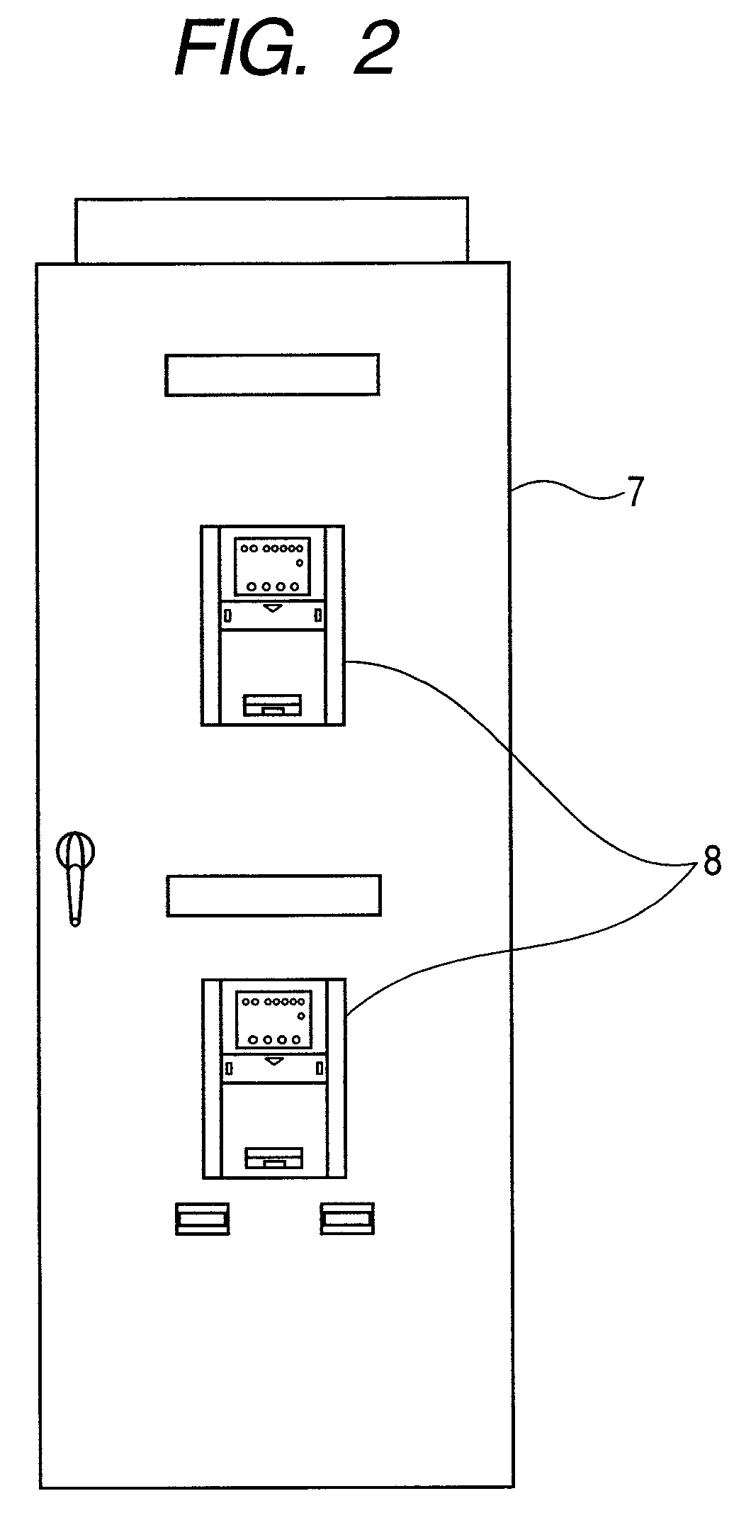
[0031]FIGS. 1 to 5 show distribution switchgear according to a first embodiment of the present invention, in which FIG. 1 is a longitudinal sectional view of distribution switchgear according to an embodiment of the invention, FIG. 2 is a front view of it, FIG. 3 is a partially sectional perspective view of the distribution switchgear shown in FIG. 1 according to an embodiment of the invention, FIG. 4 is an enlarged perspective view showing a main busbar of the distribution switchgear shown in FIG. 1 according to an embodiment of the invention, and FIG. 5 is a general connection diagram of distribution switchgear according to an embodiment of the invention.
[0032]In FIGS. 1 to 3, the inside of a housing 1 of the distribution switchgear is partitioned by partition plates 2, 3 so that an equipment room 4, a main busbar room 5 and a cable room 6 are formed in order from the front side (right in the figure). As shown in FIGS. 1 and 2, a front door 7 is provided on the front of the housin...
second embodiment
[0048]FIG. 6 is a longitudinal sectional view showing distribution switchgear according to a second embodiment of the present invention and in FIG. 6, those designated by the same reference numerals as in FIG. 1 are the same parts.
[0049]In this embodiment, a common room 36 replaces the main busbar room and cable room in the first embodiment and this common room 36 is located behind the equipment room 4, and in this common room 36, main busbars 20, link busbars 21, branch busbars 29, 30, cable sealing ends 23 and cables 24 are disposed.
[0050]According to this embodiment, the same effect as in the first embodiment can be achieved and also due to the absence of the partition plate 3 as shown in FIG. 3, maintainability and assemblability for busbars and the like are improved.
third embodiment
[0051]FIG. 7 is a longitudinal sectional view showing distribution switchgear according to a third embodiment of the present invention and in the figure, those designated by the same reference numerals as in FIG. 1 are the same parts.
[0052]In this embodiment, the cable room 6 in the first embodiment is eliminated and the cables 24 are exposed outside the housing 1. The rest of the structure is the same as in the embodiment shown in FIG. 1.
[0053]According to this embodiment, the same effect as in the above embodiments can be achieved and due to the absence of the cable room 6, the installation space is smaller, which is helpful for installation in a confined space.
PUM
 Abstract
Description
Claims
Application Information