
Interference reduction for multiple signals

a multi-signal, interference reduction technology, applied in the field of radio communication using an adaptive array, can solve the problems of severe degrade reception, different time delays and phase shifts, distortion of amplitude, phase and frequency, etc., to reduce multi-path, reduce multi-path and other shared interference, and reduce the degradation of one signal performance

Inactive Publication Date: 2009-04-14
RILLING KENNETH F
View PDF10 Cites 3 Cited by
  • Summary
  • Abstract
  • Description
  • Claims
  • Application Information

AI Technical Summary

Benefits of technology

This approach effectively enhances the performance of multiple receivers by reducing shared interference, improving signal quality, and reducing the complexity and cost associated with multiple adaptive systems, while maintaining effective interference rejection even in weak signal conditions.

Problems solved by technology

One source of interference that can severely degrade reception is multipath.
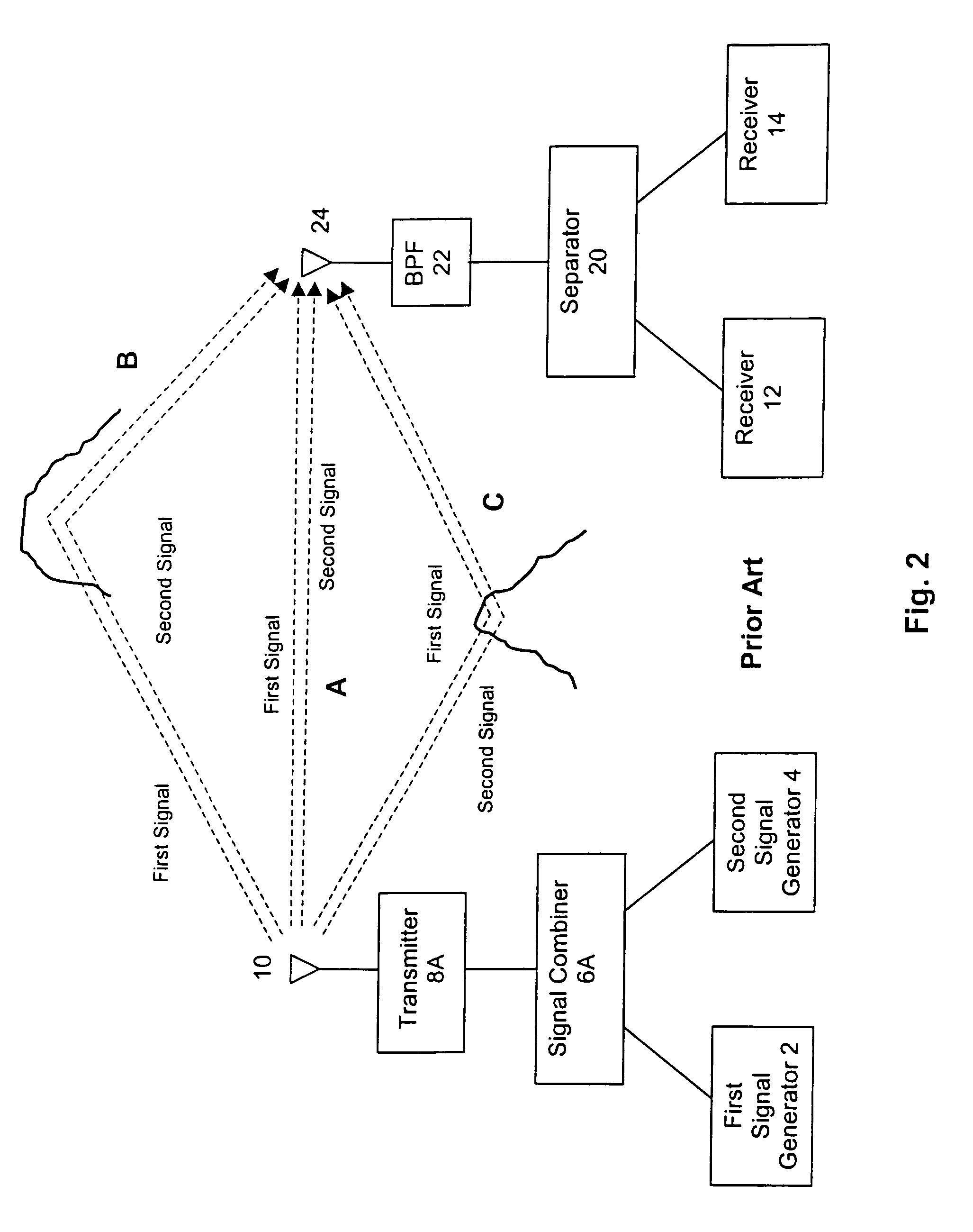
Multipath occurs when the transmitted signal arrives at the receiver's antenna over different propagation paths resulting in different time delays and phase shifts.
Multipath can cause distortion in the amplitude, phase and frequency of the received signal, which can result in deep signal strength fades, frequency selective fades, intersymbol interference, noise, etc.
Both radio signals can suffer from interference (multipath and / or other shared interference) problems and require that the interference be reduced to improve reception.
When multiple signals are present, the use of an adaptive array or adaptive filter for each signal can be expensive, complicated and occupy too much space.
For some signals, a dedicated adaptive array or adaptive filter may not provide enough performance improvement if the signal structure or available information does not lend itself to the use of an adaptive array or adaptive filter.

Method used


Image

  • Interference reduction for multiple signals
  • Interference reduction for multiple signals
  • Interference reduction for multiple signals

Examples


Embodiment Construction

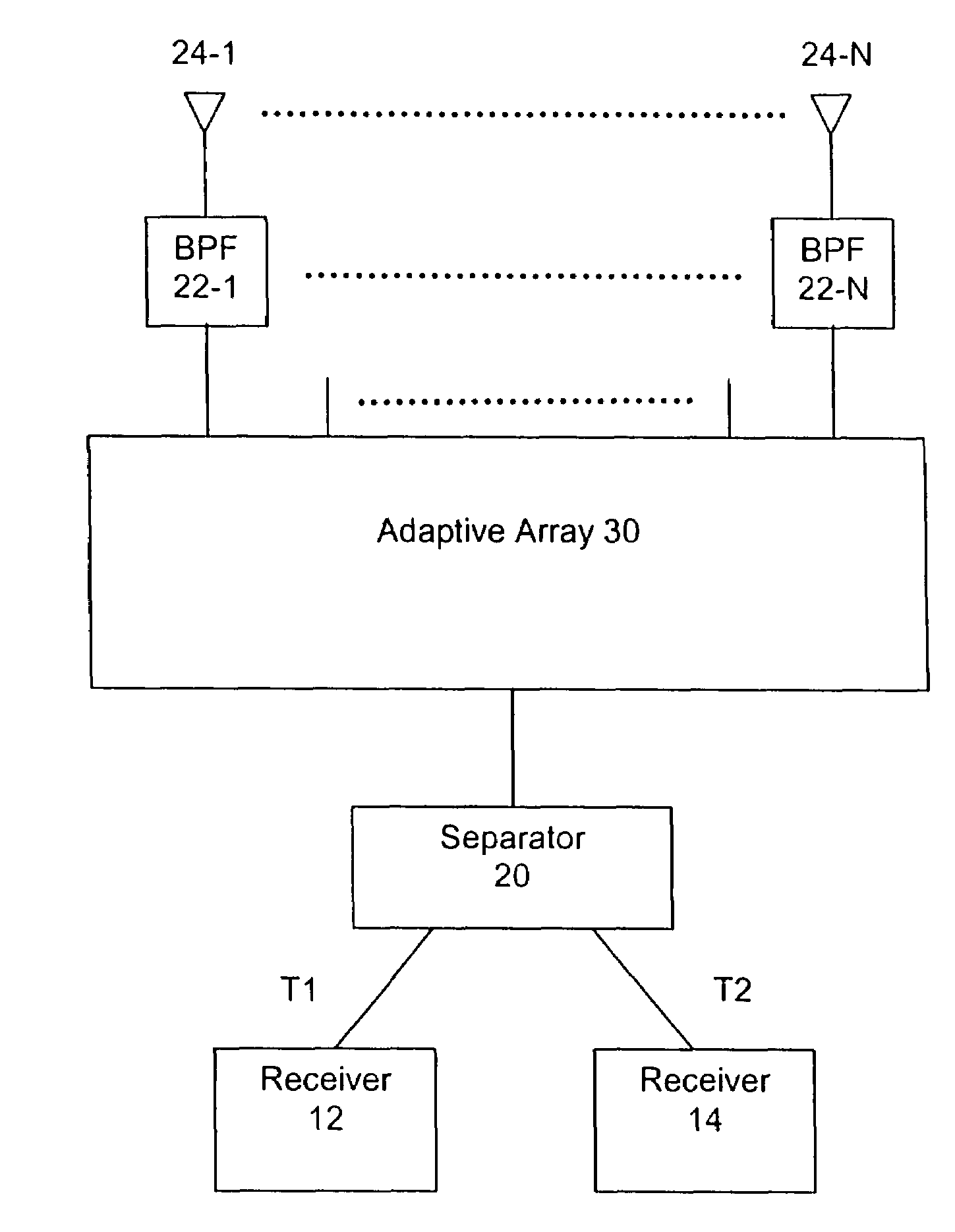
[0022]The purpose of the present invention is to use one adaptive array to improve the performance of two receivers by reducing interference (multipath or other interference that is shared) when the two radio signals occupy the same frequency channel, are transmitted from same antenna, received by the same antenna or antenna array, and are separable. In the present invention, interference other than multipath means interference shared by both radio signals.

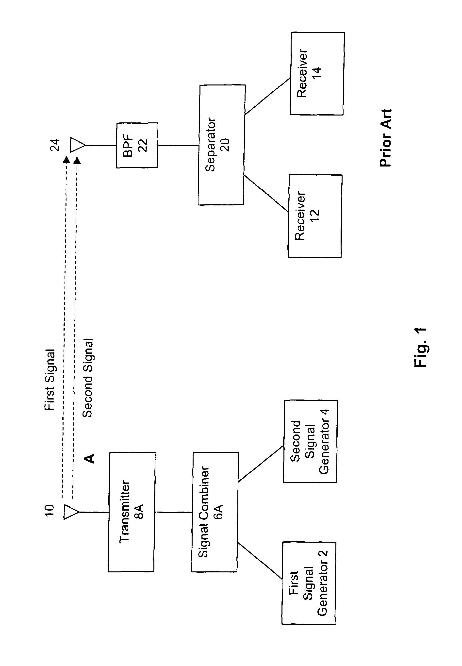
[0023]FIG. 1 shows a prior art diagram of the transmission, propagation A, and reception of first and second radio signals. They use the same transmitter 8A, transmit antenna 10 and receive antenna 24, and occupy the same frequency channel. The signals are generated by the first signal generator 2 and second signal generator 4 and coupled to the inputs of signal combiner 6A. The two signals are combined by combiner 6A in a manner that permits their separation at the receiver (discussed below). They are transmitted by the same tran...


PUM


Abstract

The present invention reduces the degradation in performance of one or more radio signals that are co-transmitted with a first radio signal from the same transmitting antenna in the same frequency channel and received by the same antenna due to multipath or other shared interference, where the one or more radio signals can be separated from the first radio signal. All received signals are coupled to the same adaptive array or adaptive filter to reduce multipath or other shared interference of the first radio signal, which reduces multipath and other shared interference in the other radio signals before they are separated and processed by their respective receivers, or the individual radio signals are separated before the first signal enters the adaptive array or adaptive filter and each of the other signals coupled to an individual associated adaptive array or adaptive filter slave weighting network with weights slaved to the weights of the adaptive array or adaptive filter of the first signal to reduce the multipath and other shared interference in all the signals.

Description

[0001]This application is a continuation of the application having Ser. No. 10 / 405,010 filed Mar. 30, 2003 now U.S. Pat. No. 7,076,228 which is Continuation-In-Part application based on a patent application filed by the same inventor on Nov. 10, 1999 and assigned Ser. No. 09 / 438,132 and entitled SIMULTANEOUS PROCESSING OF MULTIPLE SIGNALS BY AN ADAPTIVE ANTENNA having issued into U.S. Pat. No. 6,564,044 on May 13, 2003.BACKGROUND OF THE INVENTION [0002]1. Field of the Invention[0003]The present invention relates to the use of an adaptive array in radio communications and in particular to improve the performance of communications and broadcast systems that incorporate multiple signals.[0004]2. Description of the Prior Art[0005]To obtain high quality reception, communications receivers require a signal that is uncorrupted by interference, such as multipath, adjacent channel or co-channel. One source of interference that can severely degrade reception is multipath. Multipath occurs whe...

Claims


Application Information

Patent Timeline
Patent Type & Authority Patents(United States)
IPC IPC(8): H04B1/06
CPCH04L25/03885H04B1/1081H04B7/0851H04L25/03025H04B7/0848H04B7/0862H04B7/086H04B1/10H04L27/38H04L25/03019
Inventor RILLING, KENNETH F.
Owner RILLING KENNETH F
Learn More