Turbine airfoil with near-wall leading edge multi-holes cooling

a technology of airfoil and film cooling, which is applied in the direction of engine fuction, blade accessories, machines/engines, etc., can solve the problems of reducing the leading edge metal temperature of the blade, and achieve the effects of reducing the overall pressure ratio, maximizing the use of cooling air, and increasing the leading edge film coverag

Inactive Publication Date: 2009-04-21
FLORIDA TURBINE TECH
View PDF15 Cites 71 Cited by
  • Summary
  • Abstract
  • Description
  • Claims
  • Application Information

AI Technical Summary

Benefits of technology

[0013]Cooling air is supplied through the leading edge cooling supply cavity and impinges onto the backside of the airfoil leading edge inner surface. This firstly provides impingement cooling of the airfoil leading edge section. Multiple metering holes are then used for each individual impingement cavity to provide a desired pressure and flow rate to the intermediate coolant pressure cavity. Multiple impingement cavities can be used in the spanwise direction for tailoring the blade spanwise hot gas side pressure and heat load conditions. In addition, the multiple metering holes also provide backside impingement cooling to the airfoil leading edge region at much closer distance to the airfoil exterior hot surface. Internal cooling pressure for each individual impingement cavity can also be regulated by the multiple metering holes. With the use of the cooling design of the present invention, a reduction of the overall pressure ratio across the leading edge film cooling holes can be achieved. At a given cooling flow rate and lower pressure ration across the film holes, it yields a large number of leading edge film holes thus forming a multi-hole cooling mechanism for t

Problems solved by technology

Increase number of leading edge film cooling holes also increases the overall leading edge interna

Method used


Image

  • Turbine airfoil with near-wall leading edge multi-holes cooling
  • Turbine airfoil with near-wall leading edge multi-holes cooling

Examples


Embodiment Construction

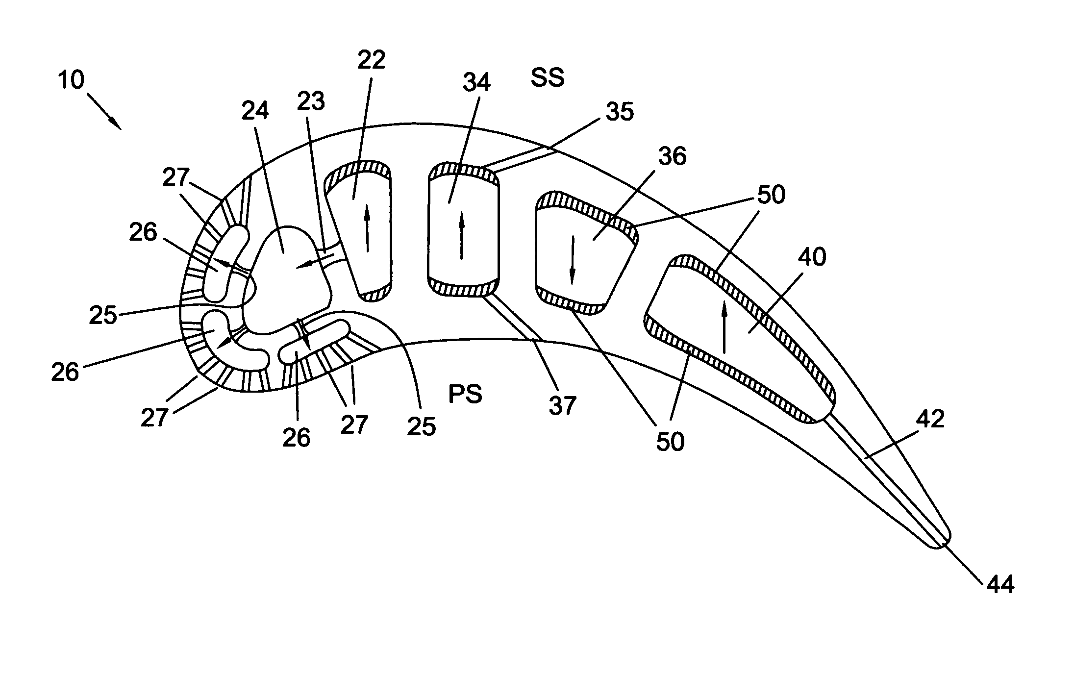
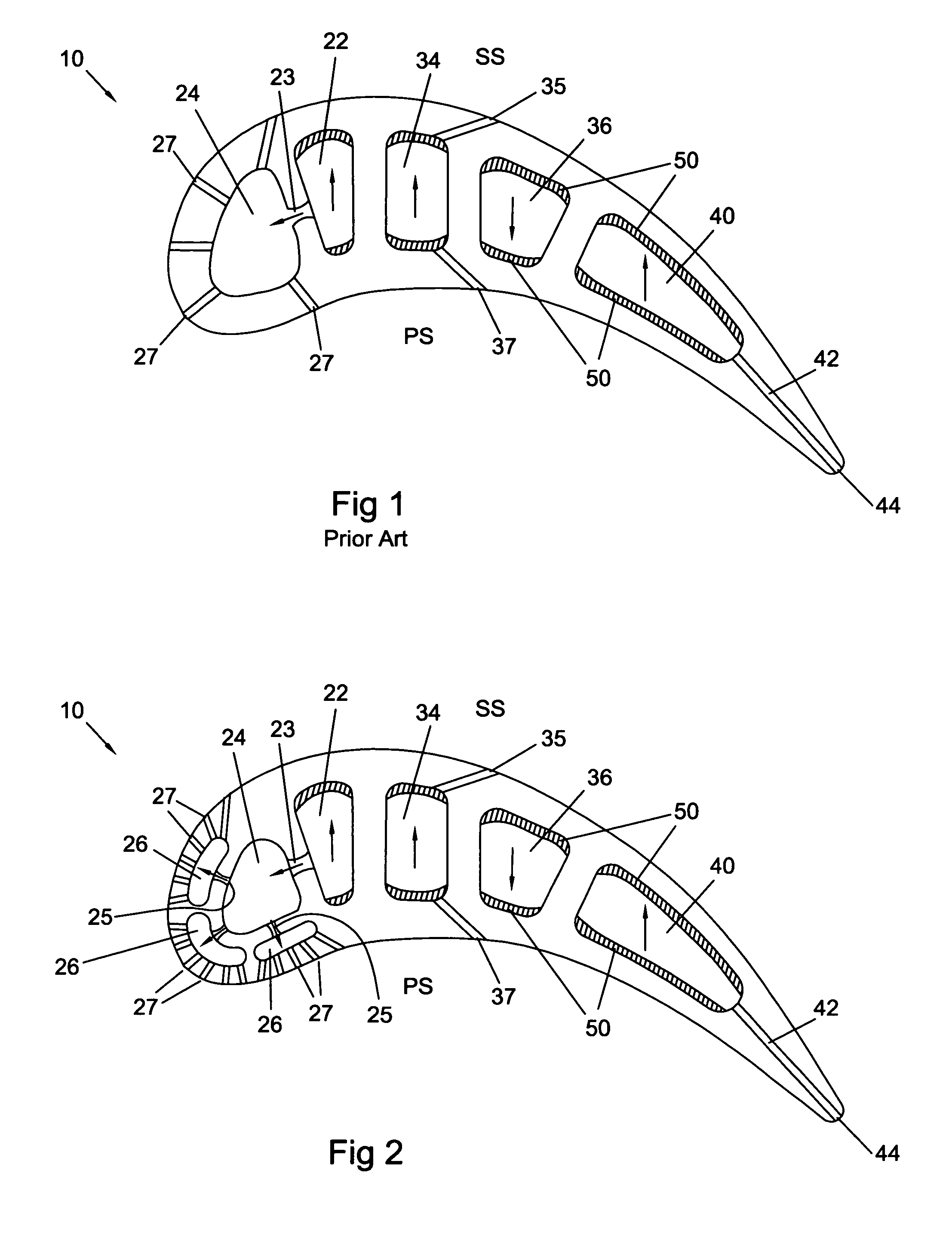
[0017]The airfoil of the present invention is shown in FIG. 2 and includes the features described above with respect to the prior art FIG. 1 airfoil. In addition, FIG. 2 includes three multi-impingement cavities 26, one on the nose of the leading edge of the airfoil, a second one on the pressure side, and a third on the suction side of the airfoil. Multi-metering holes 25 connect the impingement cavity 24 to the multi-impingement and diffusion cavities 26. Each multi-impingement and diffusion cavity 26 includes a plurality of multi-showerhead holes 27 that open onto the respective surface of the airfoil to provide film cooling.

[0018]On the pressure side multi-impingement cavity 26, the downstream-most film cooling hole 27 discharges onto the pressure side surface at a location about where the forward-most side wall of the cooling supply cavity 22 ends. On the suction side multi-impingement cavity 26, the downstream-most film cooling hole 27 discharges onto the suction side surface a...


PUM


Abstract

An air cooled airfoil used in a gas turbine engine includes a showerhead arrangement to cool the leading edge. A cooling supply cavity supplies cooling air to the airfoil, and is metered into an impingement cavity through at least one metering hole from the cooling supply cavity. A plurality of second impingement cavities are located between the first impingement cavity and the leading edge, and each second impingement cavity includes at least one second metering hole to meter cooling air into the second impingement cavity. Each second impingement cavity includes a plurality of film cooling holes to discharge cooling air to the leading edge surface of the airfoil. The second impingement cavities are located adjacent to each other, with one on the leading edge, another on the pressure side, and the third on the suction side.

Description

BACKGROUND OF THE INVENTION[0001]1. Field of the Invention[0002]The present invention relates generally to fluid reaction surfaces and more specifically to turbine airfoils with film cooling.[0003]2. Description of the Related Art Including Information Disclosed Under 37 CFR 1.97 and 1.98[0004]A gas turbine engine includes a turbine section in which a hot gas flow passes through the rotor blades and stationary vanes or nozzles to extract energy from the flow. The efficiency of the gas turbine engine can be increased by providing a higher flow temperature into the turbine. However, the temperature is limited to the material capabilities of the parts exposed to the hot gas flow.[0005]One method of allowing for higher turbine temperatures is to provide cooling of the first and second stages of the turbine. Complex internal cooling passages have been disclosed to provide high cooling capabilities while using lower flow volumes of cooling air. Since the cooling air used in the turbine ai...

Claims


Application Information

Patent Timeline
IPC IPC(8): F01D5/18
CPCF01D5/186F05D2240/121F05D2240/303F05D2260/201
Inventor LIANG, GEORGE
Owner FLORIDA TURBINE TECH
Why Eureka
Try Eureka