Structure for fixing stainless steel tubes in waste gas treatment tube

A fixed structure, exhaust gas treatment technology, applied in the direction of dispersed particle separation, chemical instruments and methods, separation methods, etc., can solve the problems of stainless steel pipes such as difficulty, high cost, secondary pollution, etc., to save space, compact distance, improve The effect of work efficiency

Inactive Publication Date: 2014-10-08
ZHEJIANG HUIER COATING ENVIRONMENTAL PROTECTION EQUIP
View PDF3 Cites 2 Cited by
  • Summary
  • Abstract
  • Description
  • Claims
  • Application Information

AI Technical Summary

Problems solved by technology

However, since plasma is an interdisciplinary subject including discharge physics, discharge chemistry, chemical reaction engineering, electronic technology and material science, the technology is not yet mature, and many low-temperature plasma exhaust gas purification devices are currently The cost is high and will still produce secondary pollution
[0003] Now imagine a low-temperature plasma exhaust gas treatment pipe, which includes a stainless steel pipe and a mace suspended in the stainless steel pipe. A galvanized pipe extends from both ends of the mace, and a part of the galvanized pipe is exposed outside the stainless steel pipe. The mace is connected to the positive pole, and the stainless steel pipe is connected to the negative pole. The mace realizes tip discharge, and an electric field is generated in the stainless steel pipe to generate a corona phenomenon. Under the acceleration of the electric field, high-energy electrons are generated. When the average energy of the high-energy electrons exceeds the target treatment When the molecular chemical bond energy is high, the molecular bond is broken, so as to achieve the purpose of eliminating gaseous pollutants; in order to improve the efficiency of waste gas treatment, the number of stainless steel pipes can be increased, but how to fix more stainless steel pipes in a limited space is more difficult

Method used


Image

  • Structure for fixing stainless steel tubes in waste gas treatment tube
  • Structure for fixing stainless steel tubes in waste gas treatment tube
  • Structure for fixing stainless steel tubes in waste gas treatment tube

Examples


Embodiment

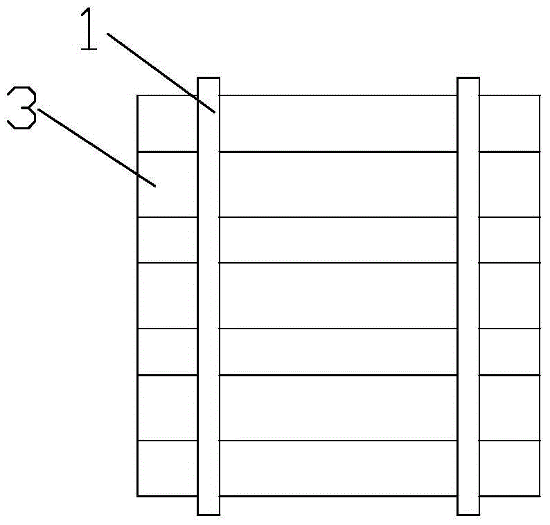
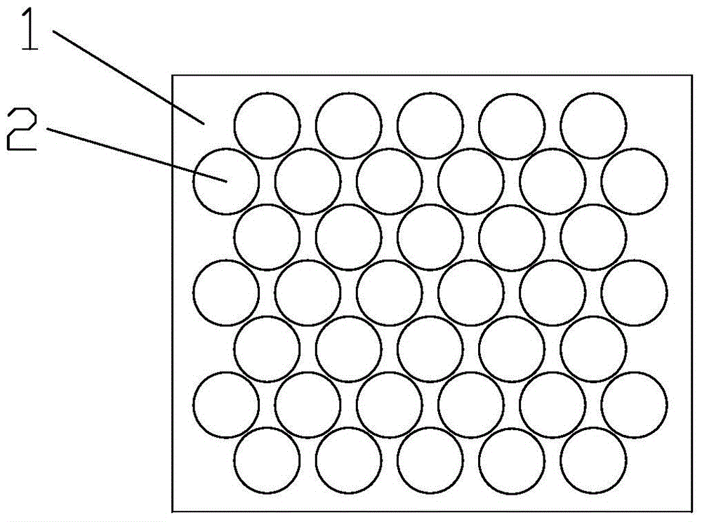
[0016] Embodiment: a kind of fixed structure of stainless steel pipe in exhaust gas treatment pipe, as figure 1 As shown, it includes two parallel and symmetrical stainless steel plates 1, and there are many pairs of identical and corresponding round holes 2 on the two sides of the stainless steel plates 1; a stainless steel pipe 3 is pierced in each pair of corresponding round holes 2 to make the stainless steel The steel pipe 3 is perpendicular to the stainless steel plate 1. Specifically, as figure 2 As shown, the circular holes 2 are arranged in multiple rows arranged horizontally, and the distance between adjacent circular holes in each row is equal; the upper middle or lower middle of a pair of adjacent circular holes in each row is one of the adjacent rows. Round holes, the centers of the three round holes are connected to form an isosceles triangle; the contact part of the stainless steel pipe 3 and the stainless steel plate 1 is fixed by welding.

[0017] In specif...


PUM


Abstract

The invention relates to a structure for fixing stainless steel tubes in a waste gas treatment tube. The structure comprises two parallel and symmetric stainless steel plates, wherein a plurality of pairs of same and corresponding circular holes are formed in the two stainless steel plates; a stainless steel tube penetrates through each pair of corresponding circular holes, so that the stainless steel tube is vertical to each stainless steel plate; the circular holes are arranged in a plurality of horizontal rows; the distances between adjacent circular holes in each row are equal; a circular hole in the adjacent row is formed in the middle above or below a pair of adjacent circular holes in each row and the circle centers of the three circular holes are connected to form an isosceles triangle. Compared with the prior art, the structure has the beneficial effects that the structure is simple to operate, achieves maximization of the number of the stainless steel tubes placed in the limited space and improves the waste gas treatment efficiency; distances are still reserved between the adjacent stainless steel tubes, but the distances between the stainless steel tubes are compact, and thus the space is saved.

Description

technical field [0001] The invention relates to the technical field of exhaust gas treatment devices, in particular to a fixing structure for stainless steel pipes in exhaust gas treatment pipes. Background technique [0002] With the development of industrial economy, the volatile waste gas produced by industries such as chemical industry, petroleum and paint is increasing day by day. These waste gases not only bring serious pollution to the environment, but also cause great harm to human health. Currently, the combustion method and oxidation method are usually used to deal with these waste gases, but these methods have defects such as high cost and easy to cause secondary pollution. At present, low-temperature plasma technology is remarkable in the treatment of gaseous pollutants. Low-temperature plasma is the fourth state of matter after solid, liquid, and gaseous states. When the applied voltage reaches the discharge voltage of the gas, the gas will be broken down, produ...

Claims


Application Information

Patent Timeline
Patent Type & Authority Applications(China)
IPC IPC(8): B01D53/32
Inventor 梁青宝
Owner ZHEJIANG HUIER COATING ENVIRONMENTAL PROTECTION EQUIP
Why Eureka
Try Eureka