Peripheral device with visual indicators to show utilization of radio component

a technology of radio components and peripheral devices, applied in the field of peripheral devices with visual indicators to show the utilization of radio components, can solve problems such as encountering problems in understanding and operating such components

Inactive Publication Date: 2009-04-21
RUCKUS WIRELESS
View PDF1 Cites 25 Cited by
  • Summary
  • Abstract
  • Description
  • Claims
  • Application Information

AI Technical Summary

Problems solved by technology

These users may encounter problems in understanding and operating such components.

Method used


Image

  • Peripheral device with visual indicators to show utilization of radio component
  • Peripheral device with visual indicators to show utilization of radio component
  • Peripheral device with visual indicators to show utilization of radio component

Examples


Embodiment Construction

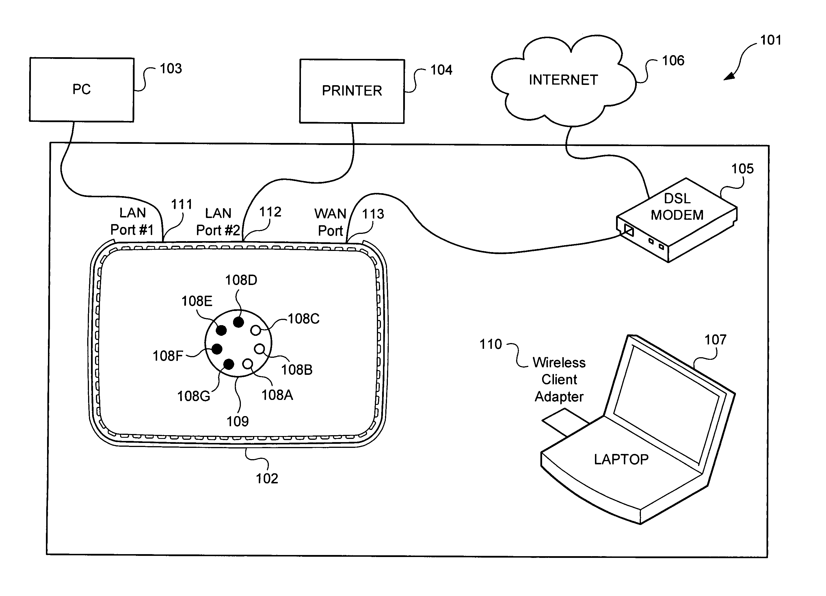
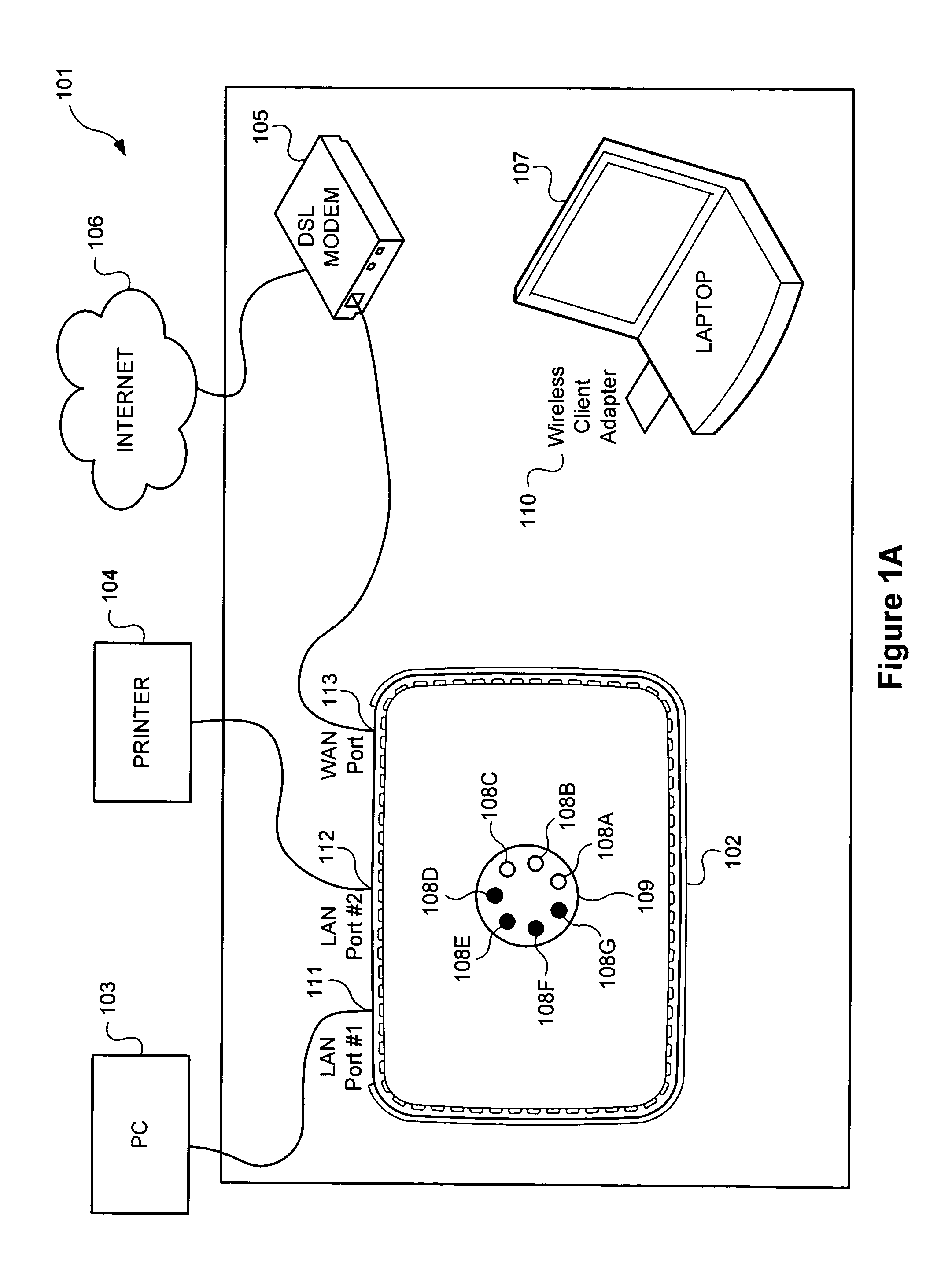
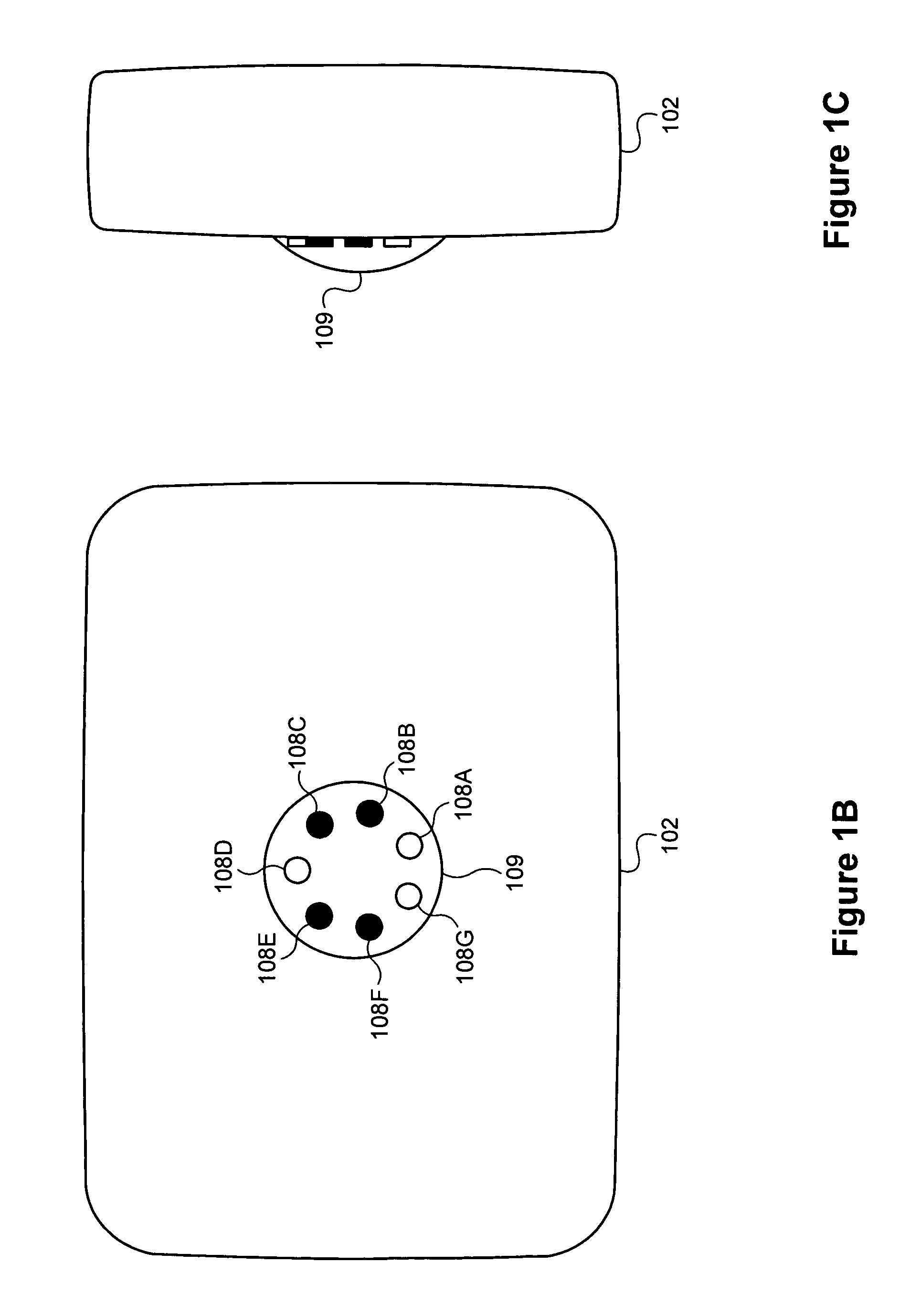
[0020]An embodiment of the invention is directed to providing users of a computer network peripheral device, such as a wireless local area network (WLAN) router, with useful information regarding utilization of a radio component, by the activation of visual indicators, such as light emitting diodes (LEDs), or an electronic display, such as a liquid crystal display (LCD). The information may comprise, for example, information such as selection of respective antennas located inside the WLAN router.

[0021]An embodiment of the invention is directed at providing users of the network peripheral device with an indication of which antenna, or antennas were selected by the network peripheral device by activating LED(s) located on the housing of the network peripheral device that correspond to the antenna(s) selected by circuitry in the network peripheral device. Circuitry in the network peripheral device selects an antenna based on factors such as RF radiation pattern incident on each antenna...


PUM


Abstract

An embodiment of the invention is directed to a network peripheral device. The network peripheral device includes a plurality of antennas, network communications electronics operable with the antennas, a plurality of electronically controllable visual indicators, and circuitry that activates the selected indicators. The network peripheral device may also include networking electronics, router functionality, a modem, a base band processor, a firewall, and / or a media access control (MAC) processor. The visual indicators may comprise light emitting diodes (LEDs). The visual indicators may correspond to a particular antenna. The visual indicators may also be arranged in a pattern corresponding to an arrangement of antennas in the plurality of antennas, or in a substantially circular pattern. Other embodiments of the invention are directed to various methods and devices.

Description

CROSS-REFERENCE[0001]This application is related to the following United States patent applications:[0002]Utility patent application for Peripheral Device with Visual Indicators, Ser. No. 11 / 173,984, invented by Patrick Rada and Smiley Kuntjoro and filed Jun. 30, 2005; and[0003]Design patent application for Peripheral Device, Ser. No. 29 / 233,436, invented by Larry Kerila, Michelle Yu and Patrick Rada, filed Jun. 30, 2005.[0004]Each of the foregoing applications are incorporated herein by reference in their entirety.BACKGROUND OF THE INVENTION[0005]As information processing, distribution and sharing through computers evolves, there is an increasing demand for networks and other forms of interconnectivity between computers. Users turn to solutions, such as network connections, wired and wireless, in order to provide increasing communication and availability of information. Some forms of networks, which may include local area networks (LANs), wide area networks (WANs), or a LAN / WAN and...

Claims


Application Information

Patent Timeline
Patent Type & Authority Patents(United States)
IPC IPC(8): H04W4/00
CPCH01Q3/30H04B7/0602H04B17/318H04B17/309H04B7/082
Inventor RADA, PATRICKKUNTJORO, SMILEY
Owner RUCKUS WIRELESS
Why Eureka
Try Eureka