

Method and system for laser amplification using a dual crystal Pockels cell
a dual crystal pockel and laser amplification technology, applied in the direction of laser details, instruments, electrical apparatus, etc., can solve the problems of reducing the peak laser intensity, fixed and not adjustable, and too is not normally adjusted, so as to reduce, eliminate, or otherwise alter the sideband
- Summary
- Abstract
- Description
- Claims
- Application Information
AI Technical Summary
Benefits of technology
Problems solved by technology
Method used
Image

Examples
Embodiment Construction
[0025]The present invention provides a system and method for reducing, eliminating, or otherwise altering sidebands in a laser pulse system. The invention is useful in optical systems using multi-element optical switches, for example, dual crystal Pockels cells, for switching of ultra-fast laser pulses.
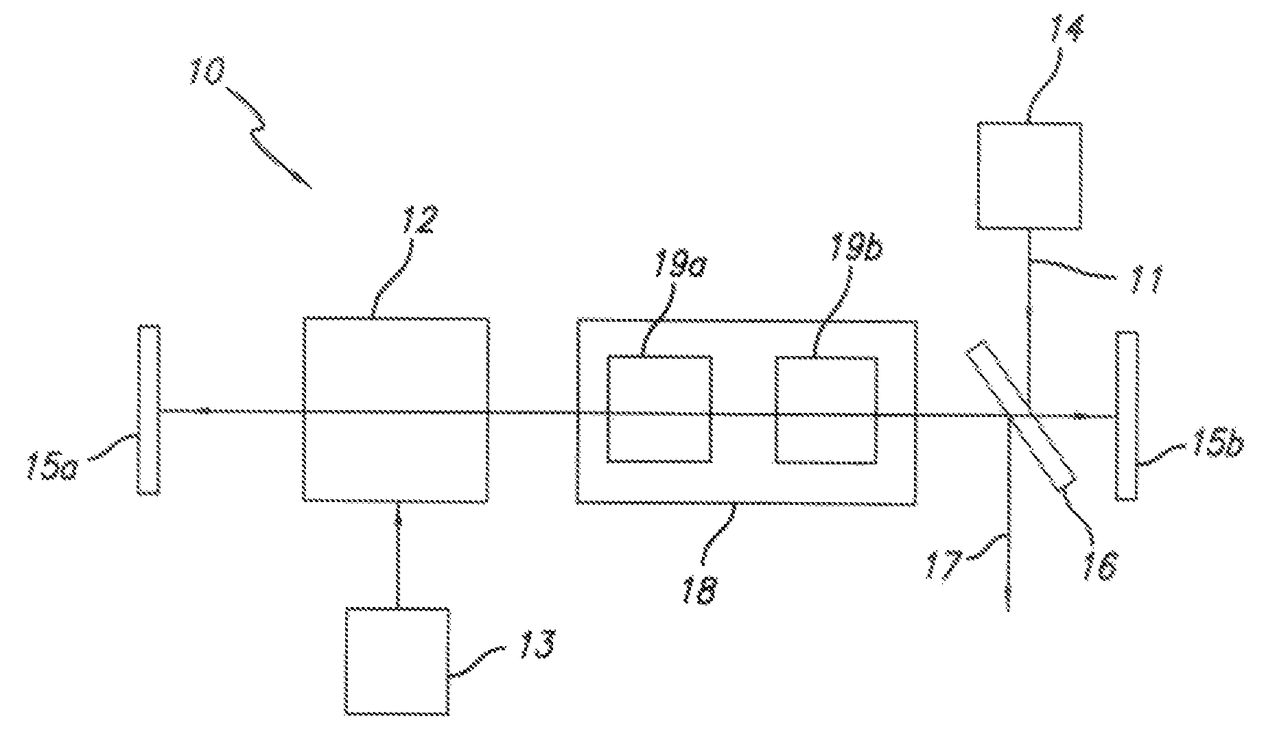
[0026]FIG. 1 shows a laser system 10 employing an optical switch comprising an adjustable Pockels cell 18 having two electro-optical crystals 19a, 19b. The gain medium 12 is disposed within the optical cavity of the system 10, the optical cavity being generally defined by two mirrored surfaces 15a, 15b. The gain medium 12 is adapted to amplify a seed pulse 11 using pump power received from a pump laser 13 or other appropriate power source. The seed pulse 11 is injected into the optical cavity from a seed laser 14. The Pockels cell 18, in conjunction with the polarizer 16, controls emission of an output pulse 17 from the optical cavity. The system may comprise various other electronic ...
PUM
| Property | Measurement | Unit |
|---|---|---|
| angle | aaaaa | aaaaa |
| offset angle | aaaaa | aaaaa |
| offset angle | aaaaa | aaaaa |
Abstract
Description
Claims
Application Information