Method of forcing 1's and inverting sum in an adder without incurring timing delay

a technology of adder and sum, applied in the field of digital logic circuits, can solve the problems of consuming much more power than ripple adder, fast adder, and large adder, and unduly increasing the area and power of the adder design

Inactive Publication Date: 2009-04-21
IBM CORP
View PDF4 Cites 10 Cited by
  • Summary
  • Abstract
  • Description
  • Claims
  • Application Information

AI Technical Summary

Benefits of technology

[0013]It is therefore one object of the present invention to provide such a design that allows for added functionality in the sum logic without introducing excessive delay or circuitry requiring large area and power.
[0014]It is another object of the present invention to provide a method of inverting a sum in an adder and forcing 1's without incurring a timing delay.

Problems solved by technology

Carry lookahead and carry-save adders are fast, but larger and consume much more power than ripple adders.
This approach can unduly increase the area and power of the adder design (a problem which is only exacerbated as the adder size grows), and can even lead to the sum logic being faster than the CLA delay when this is not desired.

Method used


Image

  • Method of forcing 1's and inverting sum in an adder without incurring timing delay
  • Method of forcing 1's and inverting sum in an adder without incurring timing delay
  • Method of forcing 1's and inverting sum in an adder without incurring timing delay

Examples


Embodiment Construction

)

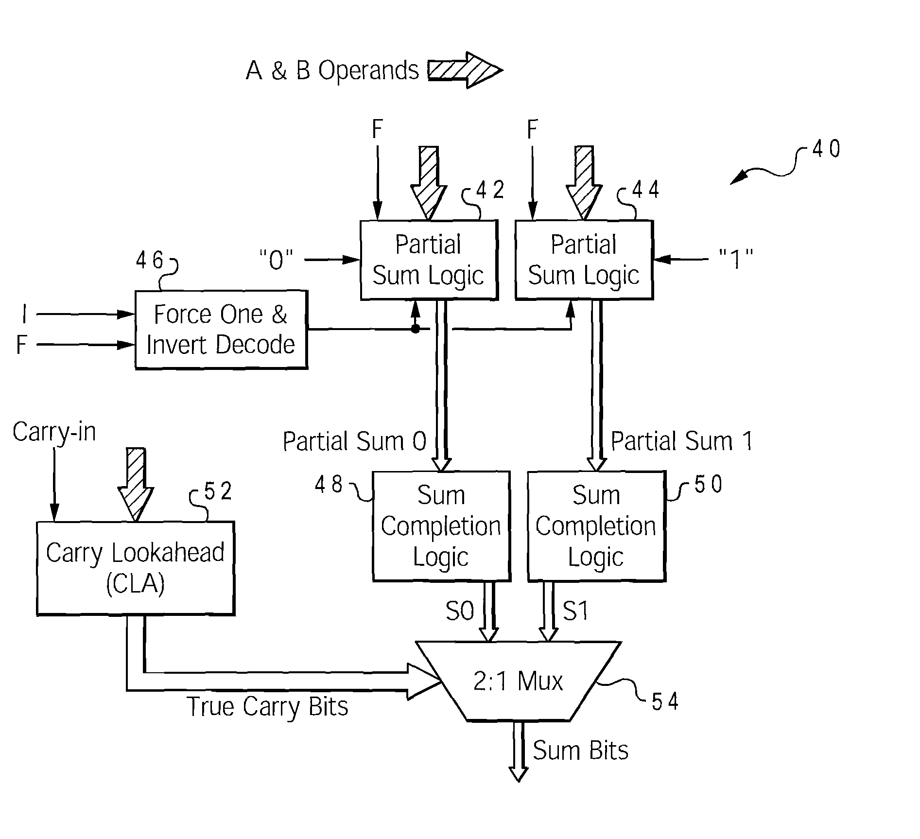
[0023]With reference now to the figures, and in particular with reference to FIG. 3, there is depicted one embodiment 40 of a summing circuit constructed in accordance with the present invention. Summing circuit 40 may comprise a 4-bit sum block that is part of a larger (e.g., 64-bit) adder. The adder so constructed may further be incorporated into a wide variety of digital logic circuits, such as execution units used by a microprocessor to operate the software programs running on a computer system (including floating-point units, fixed-point, branch units, etc.). Those skilled in the art will appreciate, however, that the use of adders is widespread throughout logic circuits and the present invention is not limited to use in execution units or general purpose data processing systems.

[0024]Summing circuit 40 is generally comprised of partial sum logic 42 and 44, force one and invert decode logic 46, sum completion logic 48 and 50, carry lookahead (CLA) block 52, and a 2:1 multiplex...


PUM


Abstract

A summing circuit for an adder decodes control signals to determine that the result should be manipulated, and generates a half-sum output which is used to produce a manipulated result based on the control signals. The half-sum output is combined with a previous carry bit to complete the sum operation. The control signals can invert the adder result, or force the result to be all 1's. These functions can be effectuated in a 3-way multiplexer that combines the operand inputs and control signals. For inversion, two separate logic circuits produce true and complement half-sums in parallel, and the appropriate half-sum is selected for the half-sum output. For a result of all 1's, a force—1 control signal pulls the half-sum output node to electrical ground and the final output is manipulated by gating the carry signals with the force—1 signal. The two functions are implemented without introducing additional delay.

Description

BACKGROUND OF THE INVENTION[0001]1. Field of the Invention[0002]The present invention generally relates to digital logic circuits, and more particularly to high-speed adders used in arithmetic logic units, such as execution units in a microprocessor or address generators of a computer system.[0003]2. Description of the Related Art[0004]Adder circuits are fundamental building blocks in all microprocessor designs. An adder, as suggested by its name, simply adds two binary numbers. Adders are used in a wide variety of arithmetic logic units such as execution units of a microprocessor, including fixed-point (or integer) units. Adders are used not only for addition operations, but also in multipliers which function by performing multiple add and shift operations. Adders are used in other areas of a conventional computer system besides the main processor, for example, in computing physical or logical addresses for memory fetch operations. Furthermore, adders are used in many other special...

Claims


Application Information

Patent Timeline
Patent Type & Authority Patents(United States)
IPC IPC(8): G06F7/507
CPCG06F7/508
Inventor GOYAL, ASHUTOSH
Owner IBM CORP
Why Eureka
Try Eureka