Combustor spring clip seal system

a technology of sealing system and turbine engine, which is applied in the direction of machines/engines, liquid fuel engines, lighting and heating apparatus, etc., can solve the problems of extended downtime, inability to easily remove the spring clip seal b>22/b>, and adversely affect the performance of turbine engines

Inactive Publication Date: 2009-04-28
SIEMENS ENERGY INC
View PDF20 Cites 19 Cited by
  • Summary
  • Abstract
  • Description
  • Claims
  • Application Information

AI Technical Summary

Problems solved by technology

Turbine engine performance can be adversely affected by fluid leakages that can occur in the combustor flow path.
However, known spring clip sealing systems can actually impede the repair process, causing extended downtime.
Consequently, the spring clip seal 22 cannot be easily removed.
During reassembly, the cut spring clip 22 and liner exit region 14 must be rewelded, making the process time consuming and raising concerns of structural integrity.
The repair of such a system is difficult because one or more components can obstruct access to the spot weld joint 26.
As a result, there is no way that a new spring clip 22 can be attached without cutting the liner 16 apart.
Again, the disassembly and reassembly of the interface becomes time-consuming and difficult.

Method used


Image

  • Combustor spring clip seal system
  • Combustor spring clip seal system
  • Combustor spring clip seal system

Examples


Embodiment Construction

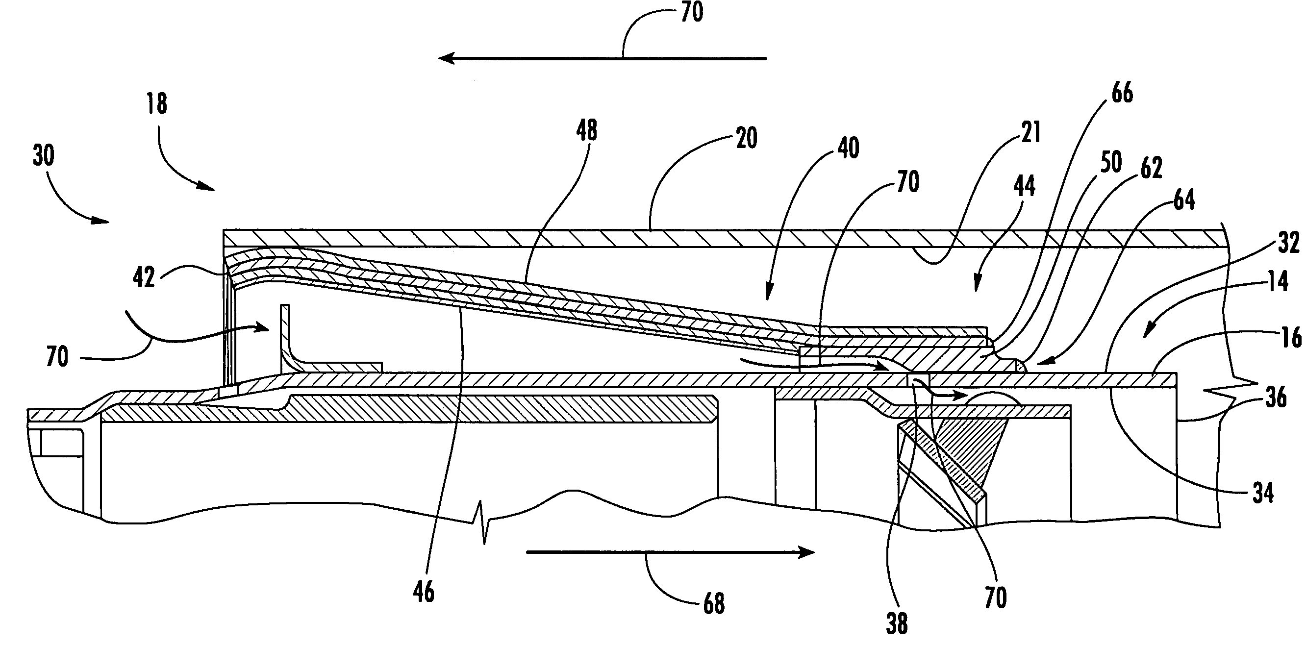
[0023]Embodiments of the present invention are directed to a spring clip seal system that can minimize the difficulties experienced with the repair, assembly and / or disassembly of prior spring clip seal systems. A system according to aspects of the invention can involve the attachment of a spring clip seal to a liner in a manner that can facilitate the separation of the spring clip seal from the liner, such as by using a welding process that does not require the base material of the spring clip seal and the liner to be melted to form the weld joint. Ideally, such a system would not appreciably affect the aerodynamic performance in the region. Embodiments of the invention will be explained in the context of one possible system, but the detailed description is intended only as exemplary. Embodiments of the invention are shown in FIGS. 4-7, but the present invention is not limited to the illustrated structure or application.

[0024]FIG. 4 shows one spring clip seal system 30 according to...


PUM


Abstract

Aspects of the invention are directed to a sealing system for the interface between a combustor liner and transition duct. The system includes a spring clip seal. A first end of the spring clip seal operatively engages the inner peripheral surface of the transition duct. A second end of the spring clip seal is indirectly attached to the liner by an insert disposed therebetween. The spring clip seal can be attached to the insert by any kind of welding process that does not involve melting of the spring clip seal and the insert, such as fillet welding. The insert and the liner can be attached in a similar manner. Because fillet welds are relatively easy to cut, the spring clip, insert and liner can be separated without the need for cutting any of these individual components. Thus, the system can facilitate the repair, disassembly and reassembly of the interface.

Description

FIELD OF THE INVENTION[0001]The invention relates in general to turbine engines and, more particularly, to a sealing system for a turbine engine.BACKGROUND OF THE INVENTION[0002]FIG. 1 shows an example of a portion of the combustor section 10 of a turbine engine. Turbine engine performance can be adversely affected by fluid leakages that can occur in the combustor flow path. One area in which such leakage can occur is the annular gap 12 defined between the exit region 14 of the combustor liner 16 and the inlet region 18 of the transition duct 20. As is known, the annular gap 12 can be sealed by the use of a spring clip seal 22. Such seals 22 are generally cylindrical cones that taper from a first diameter to a second, smaller diameter. The first diameter of the spring clip seal 22 is operatively positioned against the transition duct 20, and the second, smaller diameter is fixedly attached to a combustor liner 16. The spring clip seal 22 can accommodate relative movement between the...

Claims


Application Information

Patent Timeline
Patent Type & Authority Patents(United States)
IPC IPC(8): F01D25/24
CPCF01D9/023
Inventor OHRI, RAJEEVBOONSUAN, PLUM
Owner SIEMENS ENERGY INC
Why Eureka
Try Eureka