
High resolution head mounted projection display

a projection display and high resolution technology, applied in the field of projection displays, can solve the problems of complex tradeoffs in the design of the hmpd, optics is not optimized for detection and recognition capabilities, and the weight of the hmpd components, and achieve the effect of increasing the brightness of the imag

Inactive Publication Date: 2009-04-28
ARMY US SEC THE THE
View PDF7 Cites 10 Cited by
  • Summary
  • Abstract
  • Description
  • Claims
  • Application Information

AI Technical Summary

Benefits of technology

[0018]It is a further object of the invention to incorporate projective optics to eliminate the requisite use of an external retro-reflective screen.
[0020]It is another object of the invention to be light weight with low moment of inertia with respect to the user's neck.
[0021]It is yet another object of the invention to clearly display a target large enough to identify, along with a wide enough field of view to visually stabilize the target.
[0023]In a yet additional aspect of the invention, a second retro-reflective screen can be mounted below the beam splitter so that the split rays from the beamsplitter will recombine to create image with enhanced brightness.

Problems solved by technology

Therefore, the design of the HMPD represents complex tradeoffs that also include the size and weight of the HMPD components.
However, the optics is not optimized for detection and recognition capabilities, particularly since the see-through design decreases sensitivity for detection and recognition.
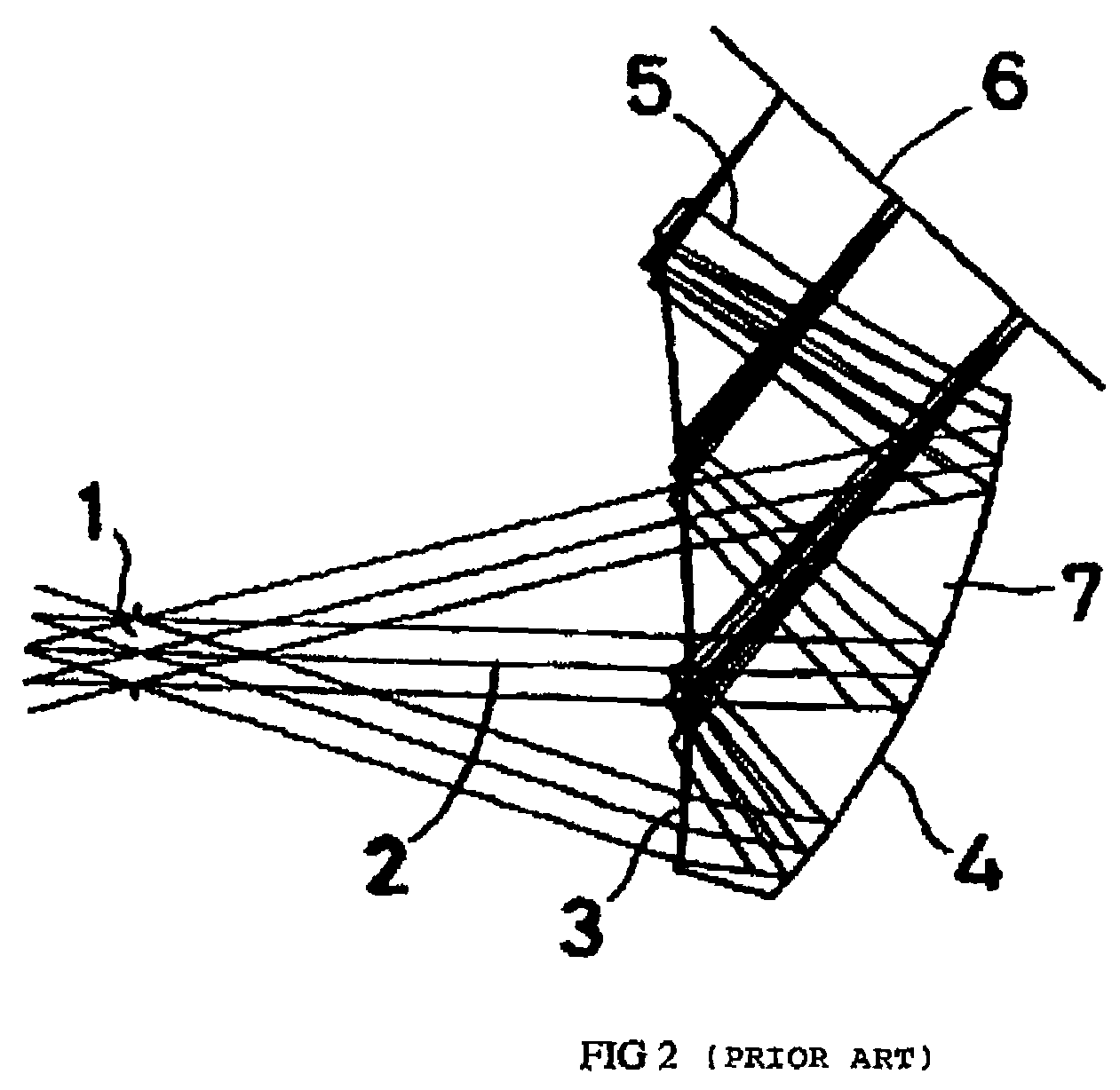
The main disadvantage of the prism is the ability to achieve acceptable optical performance over a large FOV.
The off-axis optical surfaces produce large amounts of aberrations such as astigmatism and distortion.
In addition, chromatic aberration is induced to a single glass material.
The performance of the prism can be improved by adding an aspheric surface in place of spherical surfaces to reduce the large off-axis aberration to achieve a reasonable optical performance, but the design still has limitations in correcting optical aberrations having only three working surfaces.
While the off-axis prism provides a compact lens, detection and recognition capabilities are degraded by the aberration.
As can be appreciated, the application of the optimal HMPD display is complex.
Existing HMPDs are limited in their ability to support detection and recognition requirements, an especially important requirement in military ground operations or in aircraft, ship and harbor operations.
These design limitations include, but are not limited to inadequate display resolution and field of view, limited graphics capabilities, and significant depth perception and peripheral vision problems.

Method used


Image

  • High resolution head mounted projection display
  • High resolution head mounted projection display
  • High resolution head mounted projection display

Examples


Embodiment Construction

[0032]Before explaining the disclosed embodiments of the present invention in detail, it is to be understood that the invention is not limited in its application to the details of the particular arrangements shown since the invention is capable of other embodiments. Also, the terminology used herein is for the purpose of description and not of limitation.

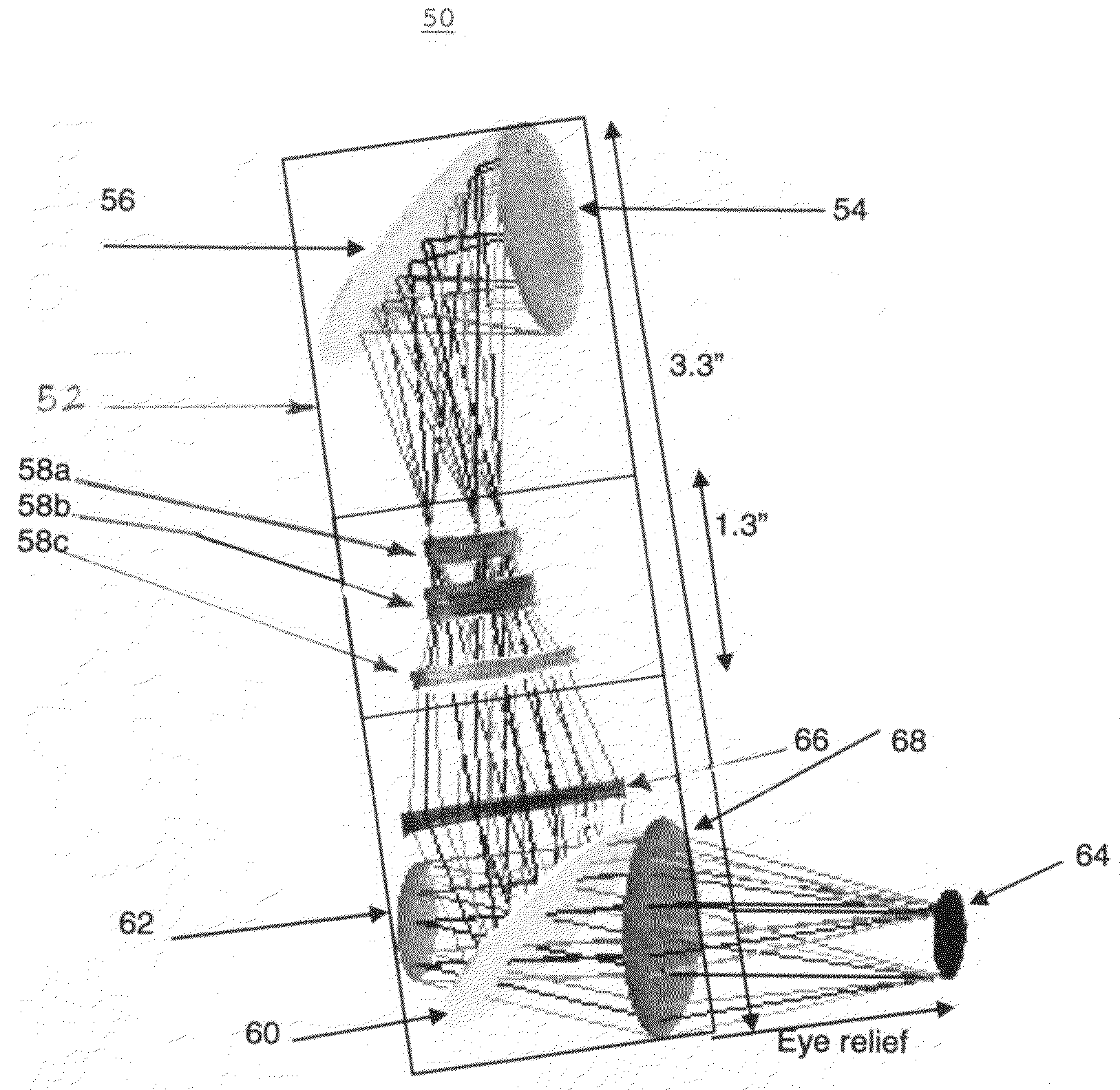
[0033]Referring to FIG. 3, an exemplary embodiment is illustrated generally at 50. A housing 52 contains an optics system which includes a miniature display 54, a mirror 56, a projection lens, preferably a landscape lens 58a,b,c, a beam splitter 60, and a retro-reflective screen (also referred to as a retro-reflector) 62 for outputting the rays to an eye 64. A second lens 66 with a Focal Number (Fno.) equal to about 1 and generally between 0.1 and 3.0 is located between the landscape lens and the beam splitter. A third lens 68 with an Fno. equal to about 1 and generally between 0.1 and 3.0 is located between the beam splitter 60 and...


PUM


Abstract

An exemplary embodiment of the invention relates to an on-axis or near on-axis optical head mounted projection display optical assembly for transmitting and magnifying a real image to an eye. The assembly comprises a miniature display, a projection lens for receiving the light rays from the display, a second lens positioned to receive the light from the projection lens, a beam splitter positioned for receiving and splitting the light rays from the second lens, a retro-reflective screen positioned for receiving the reflected portion of the split light rays from the beam splitter, and then reflecting the portion of split light rays wherein the portion of split light rays passes through the beam splitter. A third lens is positioned to receive the portion of split light rays from the retro-reflective screen and through the beam splitter.

Description

CROSS-REFERENCE TO RELATED APPLICATIONS[0001]Not ApplicableSTATEMENT REGARDING FEDERALLY SPONSORED RESEARCH OR DEVELOPMENT[0002]Not ApplicableREFERENCE TO A SEQUENCE LISTING, A TABLE OR A COMPUTER PROGRAM LISTING APPENDIX SUBMITTED ON A COMPACT DISC[0003]Not ApplicableBACKGROUND OF THE INVENTION[0004]1. Field of the Invention[0005]This invention relates generally to projection displays and more particularly to head-mounted projection displays.[0006]2. Description of the Related Art[0007]Head Mounted Projection Displays (hereafter, HMPDs) have traditionally been, and are currently utilized in a variety of applications including maintenance, training, entertainment, and operations, including military operations. The term HMPD refers to a visual display that is mounted on a head or alternatively on, or inside a helmet with an image provided by an image source such as a liquid crystal display, a cathode ray tube or some other source being generally well known. The HMPD is positioned suc...

Claims


Application Information

Patent Timeline
Patent Type & Authority Patents(United States)
IPC IPC(8): G02B27/14
CPCG02B27/0172G02B2027/011G02B2027/0116G02B2027/0123
Inventor SOTTILARE, ROBERT ANTHONYMARTINS, RICARDO F.
Owner ARMY US SEC THE THE
Learn More