Vibrating inertial rate sensor utilizing skewed drive or sense elements

a technology of drive or sense element and vibration inertial rate, which is applied in the direction of acceleration measurement using interia force, turn-sensitive devices, instruments, etc., can solve the problems of affecting the overall uniformity and ability to maintain the desired oscillation mode, the need to regularly compromise the aspiration, and the cost and complexity of gyros, so as to achieve better resonance performance, large signal-to-noise ratio, and greater symmetry

a technology of drive or sense element and vibration inertial rate, which is applied in the direction of acceleration measurement using interia force, turn-sensitive devices, instruments, etc., can solve the problems of affecting the overall uniformity and ability to maintain the desired oscillation mode, the need to regularly compromise the aspiration, and the cost and complexity of gyros, so as to achieve better resonance performance, large signal-to-noise ratio, and greater symmetry

US7526957B2Inactive Publication Date: 2009-05-05WATSON INDUSRIES

Image

  • Vibrating inertial rate sensor utilizing skewed drive or sense elements
  • Vibrating inertial rate sensor utilizing skewed drive or sense elements
  • Vibrating inertial rate sensor utilizing skewed drive or sense elements

Examples


Embodiment Construction

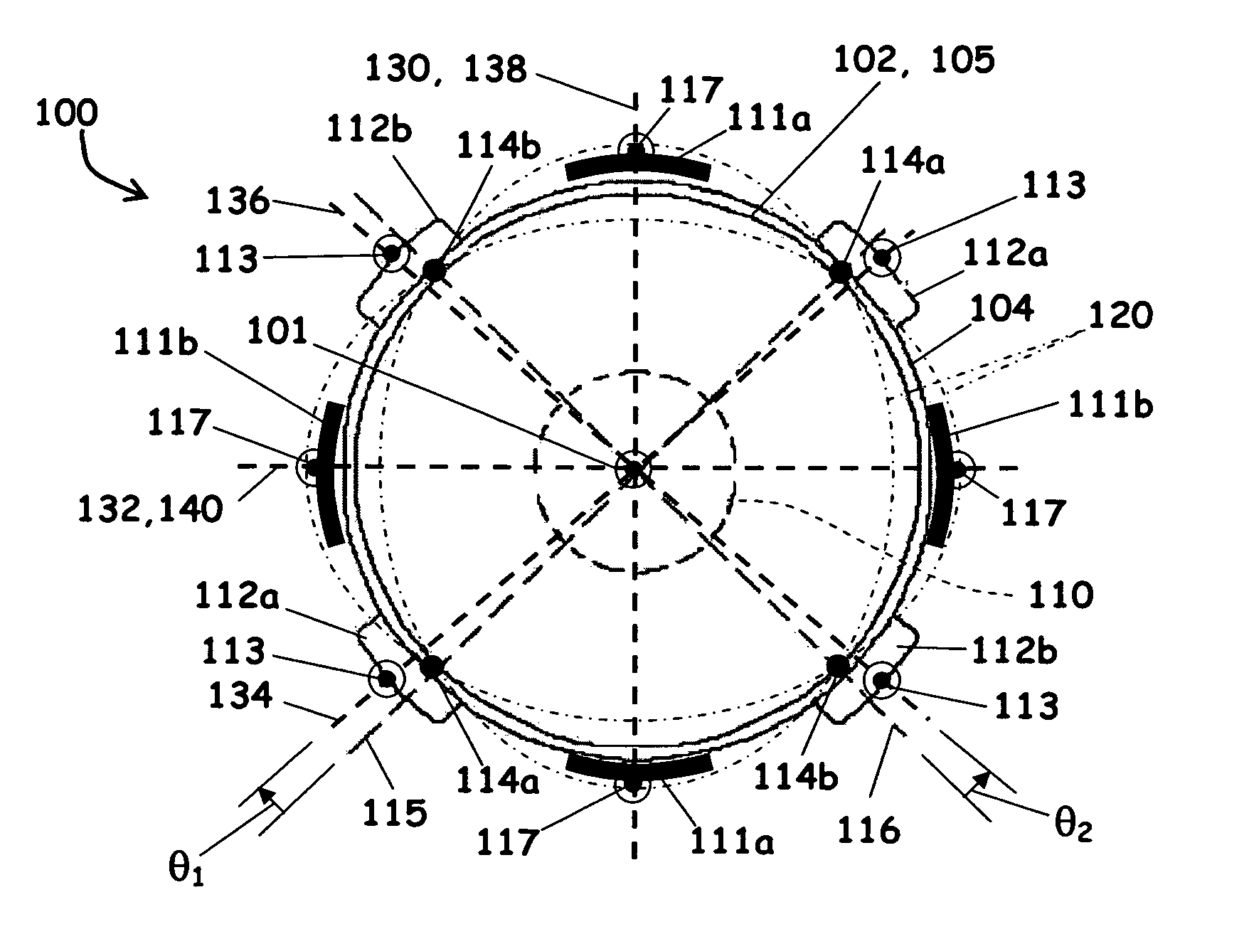
[0041]Referring to FIG. 1, a split drive electrode assembly 30 for correcting undesirable oscillation alignment as is known in the prior art is depicted. The split drive electrode assembly 30 is comprised of a resonator 32 having a generally cylindrical cross-section and features two diametrically opposed drive electrodes 34 and 36, one of which is split into two electrically isolated electrodes 36a and 36b.

[0042]In operation, drive electrode 34 provides a drive signal to generate an oscillation or vibration pattern 38 (shown in phantom) characterized by a pair of node reference axes 40a and 40b, and a pair of antinode reference axes 42a and 42b. The node reference axes 40a and 40b are defined by the points on the vibration pattern 38 where the amplitudes of the oscillation are at local minima. In contrast, the antinode reference axes 42a and 42b are defined by the points on the vibration pattern 38 where the amplitudes of the oscillation are at local maxima. Functionally, the spli...


PUM


Abstract

A vibrating inertial rate sensor has sense elements that operate on axes that are rotationally skewed from a node reference axis, enabling both a rate sense and a drive sense determination. Alternatively, the skew may be applied to rotationally offset the drive elements from antinode reference axes to affect active torquing of the gyroscope. The skewed sensing scheme may be applied to vibratory systems having one or more node axes. The skewed drive scheme may be applied to vibratory systems having two or more node axes to affect active torquing.

Description

RELATED APPLICATIONS[0001]This application is a continuation-in-part of and claims priority to U.S. patent application Ser. No. 11 / 379,169, filed 18 Apr. 2006 now abandoned, which is hereby incorporated by reference herein in its entirety. This application further claims priority to U.S. Provisional Patent Application No. 60 / 826,046, filed 18 Sep. 2006, which is hereby incorporated by reference herein in its entirety.TECHNICAL FIELD[0002]The present disclosure relates generally to angular rate sensors, and more particularly to vibrating element angular rate sensors used, for example, as gyroscopes.BACKGROUND OF THE DISCLOSURE[0003]Instrumentation sensors that operate on a principle of vibration of constrained actuator masses are known in the art. Angular rate gyroscopes make use of the principle of inertia to measure the rate of rotation through an angle with respect to a sensing axis. One type of angular rate gyroscope is the solid-state gyroscope. Vibrating rate gyroscopes utilize...

Claims


Application Information

Patent Timeline
05 May 2009
Publication
US7526957B2
IPC
G01P9/04; G01C19/00; G01C19/56; G01C19/5691
CPC
G01C19/56; G01C19/5691
Inventors
WATSON, WILLIAM S.