Chain tensioner

a chain tensioner and chain technology, applied in the direction of threaded fasteners, bolts, gearing, etc., can solve the problems of insufficient assembly, troublesome and time-consuming assembly, and difficult to operate the chain tensioner with high accuracy, so as to achieve easy assembly, constant clearance, and accurate operation of the chain tensioner

Active Publication Date: 2009-05-05
NTN CORP
View PDF16 Cites 16 Cited by
  • Summary
  • Abstract
  • Description
  • Claims
  • Application Information

AI Technical Summary

Benefits of technology

[0011]With this arrangement, even if the housing is formed of a soft material such as an aluminum alloy, the housing will never be deformed when the support pin is pressed into the pin hole to such an extent as to cause changes in the dimensions of the inner wall of the cylinder chamber and / or strains in the inner wall of the cylinder chamber. Thus, the clearance between the cylinder chamber and the plunger is kept constant. This ensures smooth sliding of the plunger and thus accurate operation of the chain tensioner.
[0013]The locking lever is pivoted about the support pin to engage the locking pin, thereby keeping the plunger pushed into the cylinder chamber. When the chain is driven in this state, the plunger is pushed in by the chain. When the plunger is pushed in, the locking pin separates from the locking lever, so that the locking lever pivots by gravity back to its original position. Thus, the plunger is automatically released merely by driving the chain without the need to carry out special steps for releasing the plunger. The chain tensioner can thus be assembled easily.
[0016]Such a locking lever is sufficiently rigid, so that it can more reliably keep the plunger pushed into the cylinder chamber when it is in engagement with the locking pin.
[0018]After the plunger has been released, the locking lever is freely pivotable about the support pin. Thus, due to vibrations of the vehicle and / or the engine, the locking lever may pivot to its horizontal position. If the plunger is pushed in when the locking lever has pivoted to the horizontal position, the locking lever may get caught by the pin. But by receiving the support pin in the elongated holes formed in the side members, the locking lever can move backward together with the plunger when the chain is tensioned. Thus, the chain is prevented from being subjected to excessive tension.
[0020]With this arrangement, too, even if the housing is formed of a soft material such as an aluminum alloy, the housing will never be deformed when the pin is pressed into the pin hole to such an extent as to cause changes in the dimensions of the inner wall of the cylinder chamber and / or strains in the inner wall of the cylinder chamber. Thus, it is possible to maintain a constant clearance between the cylinder chamber and the plunger. This ensures smooth sliding of the plunger and thus accurate operation of the chain tensioner.
[0021]As soon as the plunger is pushed in by the chain, and the free end of the short arm separates from the plunger, the short arm retracts into the through hole. Thus, the plunger can be released automatically by pushing the plunger with the chain. The chain tensioner can thus be assembled easily.

Problems solved by technology

Since the plunger has to be kept pushed in the cylinder chamber against the force of the spring while assembling the chain tensioner, assembly is troublesome and time-consuming.
While this chain tensioner can be assembled more easily than the first mentioned chain tensioner, assembly is still not sufficiently easy because the pin has to be pulled out after the chain tensioner has been assembled.
This makes it difficult to operate the chain tensioner with high accuracy.

Method used


Image

  • Chain tensioner
  • Chain tensioner
  • Chain tensioner

Examples


first embodiment

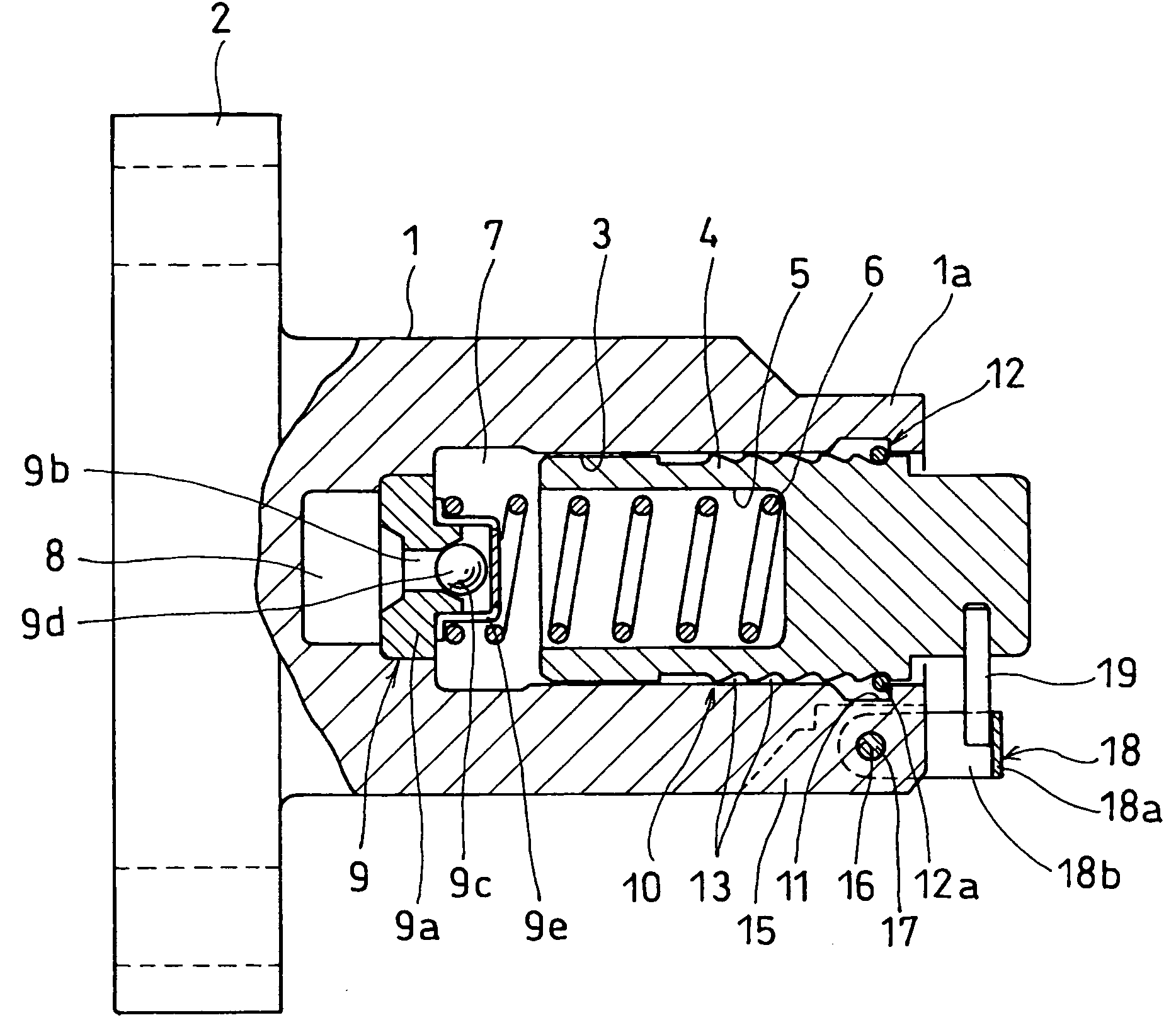
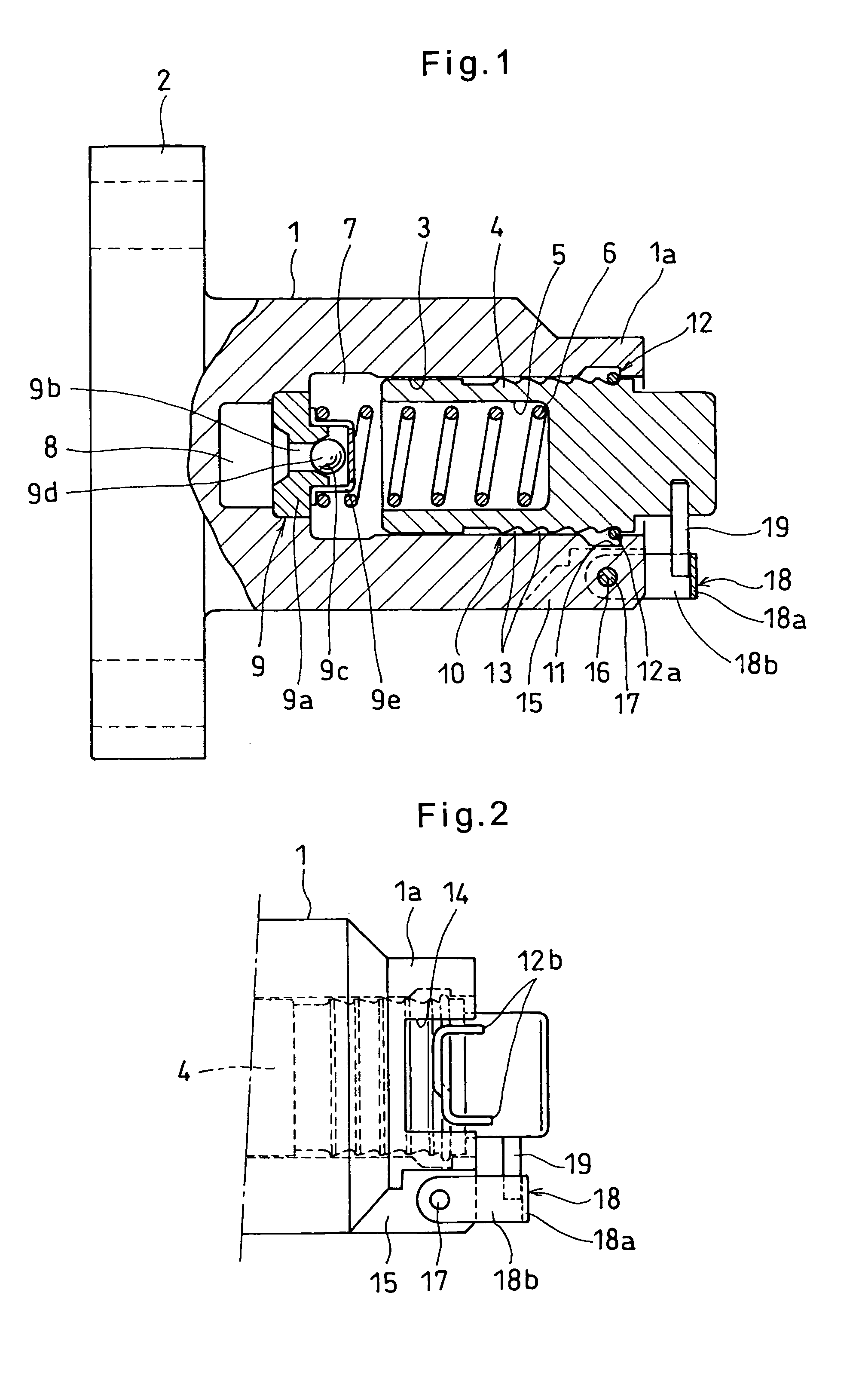
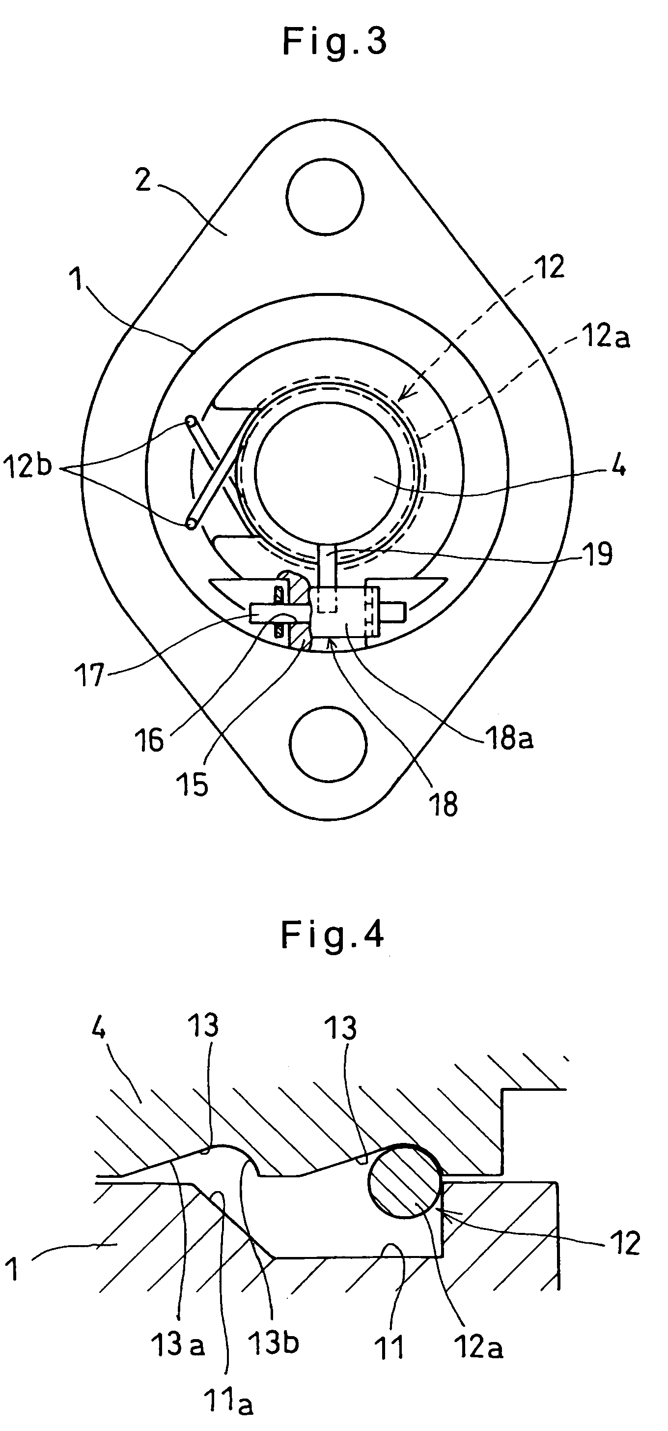
[0038]Referring first to FIGS. 1-4, the chain tensioner of the first embodiment includes a cylindrical housing 1 formed of a soft material such as an aluminum alloy and having a small-diameter portion 1a at a front end thereof and an integral mounting flange 2 at a rear end.

[0039]The housing 1 has a cylinder chamber 3 having an opening at the front end thereof. A plunger 4 is slidably mounted in the cylinder chamber 3.

[0040]The plunger 4 has a spring mounting chamber 5 having an opening at its rear end. A spring 6 is mounted in the spring mounting chamber 5 to bias the plunger 4 outwardly of the housing 1.

[0041]A pressure chamber 7 is defined in the cylinder chamber 3 by the plunger 4. The pressure chamber 7 and the spring mounting chamber 5, which communicates with the pressure chamber 7, are filled with hydraulic oil which is supplied through an oil supply passage 8 formed in the end wall of the cylinder chamber 3. A check valve 9 is provided in the oil supply passage 8 at its end...

third embodiment

[0063]In contrast, the locking lever 18 of the third embodiment can move backward in the state of FIG. 9 because the pin 17 is received not in circular holes but in the elongated holes 18c. Thus, the plunger 4 can also move backward in the state of FIG. 9. This prevents the chain 32 from being subjected to excessive tension.

[0064]The fourth embodiment, shown in FIGS. 10 and 11, differs from the first embodiment in that an L-shaped pin 20 is used to keep the plunger 4 pushed into the cylinder chamber 3.

[0065]Specifically, the upper front end of the housing 1 is cut out to define a shoulder 21. A pin hole 22 is formed in the shoulder 21 so as to extend parallel to the axis of the cylinder chamber 3. A through hole 23 is formed in the cylinder 1 in the bottom of the cutout so as to extend to the inner wall defining the cylinder chamber 3. The L-shaped pin 20 has the end of its longer arm inserted in the pin hole 22 and the shorter arm 20a inserted in the through hole 23.

[0066]Otherwise...

fifth embodiment

[0073]The backward movement restricting arrangement 10 of the fifth embodiment includes a screw rod 27 inserted in a hole 25 formed in the plunger 4 and having an opening at the rear end thereof. The screw rod 27 is formed with a screw thread 28 on its outer surface which is in threaded engagement with a screw thread 26 formed in the inner wall of the hole 25. Each of the screw threads 26 and 28 has a pressure flank F1 which bears the force applied to the plunger 4, and a clearance flank F2. The pressure flank F1 has a greater flank angle than the clearance flank F2, so that the threads 26, 28 have a serration-like longitudinal section as clearly shown in FIG. 12. A spring 6 is mounted between the plunger 4 and the screw rod 27 to bias them away from each other. The threads 26 and 28 have such a lead angle that when the pushing force applied to the plunger disappears, the plunger can move toward and away from the screw rod 27 while turning relative to the screw rod 27 under the forc...


PUM


Abstract

A chain tensioner includes a housing having a cylinder chamber. A plunger is slidably mounted in the cylinder chamber. A spring is mounted in the cylinder chamber to bias the plunger outwardly of the cylinder chamber. The plunger has a radially extending locking pin at its lower portion near its front end. The housing is formed with a pin hole extending substantially perpendicular to an axis of the cylinder chamber near the front end of the housing and under the cylinder chamber. The chain tensioner further includes a support pin inserted in the pin hole, and a locking lever supported on the support pin so as to be pivotable about the support pin. The locking lever can engage the locking pin when the plunger is sufficiently pushed into the cylinder chamber, thereby keeping the plunger pushed in the cylinder chamber.

Description

BACKGROUND OF THE INVENTION[0001]This invention relates to a chain tensioner for keeping a constant tension in a chain of a chain transmission device, particularly one for driving camshafts.[0002]One conventional chain tensioner of this type includes a plunger inserted in a cylinder chamber formed in a housing, and a spring for biasing the plunger outwardly of the cylinder chamber. A pressure chamber is defined between the bottom of the housing and the inner end of the plunger. The pressure chamber is filled with hydraulic oil supplied through an oil supply passage formed in the housing to damp the pushing force applied to the plunger.[0003]To assemble such a chain tensioner, the spring is inserted into the cylinder chamber, and the plunger is pushed into the cylinder chamber while compressing the spring. Then, with the plunger kept pushed in the cylinder chamber against the force of the spring, the housing is secured to a stationary member. Since the plunger has to be kept pushed i...

Claims


Application Information

Patent Timeline
Patent Type & Authority Patents(United States)
IPC IPC(8): F16H7/08A41F1/00E05C3/02F16B33/02
CPCF16H7/0836F16H2007/0806F16H2007/0812Y10T24/45534F16H2007/0855F16H2007/0859F16H2007/0878F16H2007/0853Y10T292/1043Y10T292/1063Y10T292/444
Inventor SATO, SEIJIIZUTSU, TOMOYOSHIKITANO, SATOSHIHAYAKAWA, HISASHI
Owner NTN CORP
Why Eureka
Try Eureka