Vibratory gyroscope

a gyroscope and vibration technology, applied in the field of vibration gyroscopes, can solve the problems of reducing the s/n ratio and gyro resolution, and it is possible to obtain a low-sensitivity piezoelectric gyroscope, and achieve the effect of suppressing the generation of vibrations of the detection arms along the reference plan

Inactive Publication Date: 2009-05-05
JAPAN AVIATION ELECTRONICS IND LTD
View PDF7 Cites 10 Cited by
  • Summary
  • Abstract
  • Description
  • Claims
  • Application Information

AI Technical Summary

Benefits of technology

[0028]According to the vibratory gyroscope of the foregoing aspect of this invention, occurrence of resonance of the drive arms and the detection arms can be suppressed and, further, spurious resonance of unwanted components generated by vibrations of the drive arms in the reference plane can be shifted to the outside of a use frequency band. As a result, generation of vibrations of the detection arms along the reference plane is suppressed. Therefore, the high-sensitivity and high-resolution vibratory gyroscope can be provided.

Problems solved by technology

Accordingly, there is a drawback of causing a reduction in S / N ratio and gyro resolution.
That is, as a result of making such a configuration on an experimental basis and evaluating it, it was only possible to obtain a low-sensitivity piezoelectric gyroscope.

Method used


Image

  • Vibratory gyroscope
  • Vibratory gyroscope
  • Vibratory gyroscope

Examples


exemplary embodiment 1

[0037]Referring to FIG. 3, a description will be given of a vibratory gyroscope according to exemplary embodiment 1 of this invention.

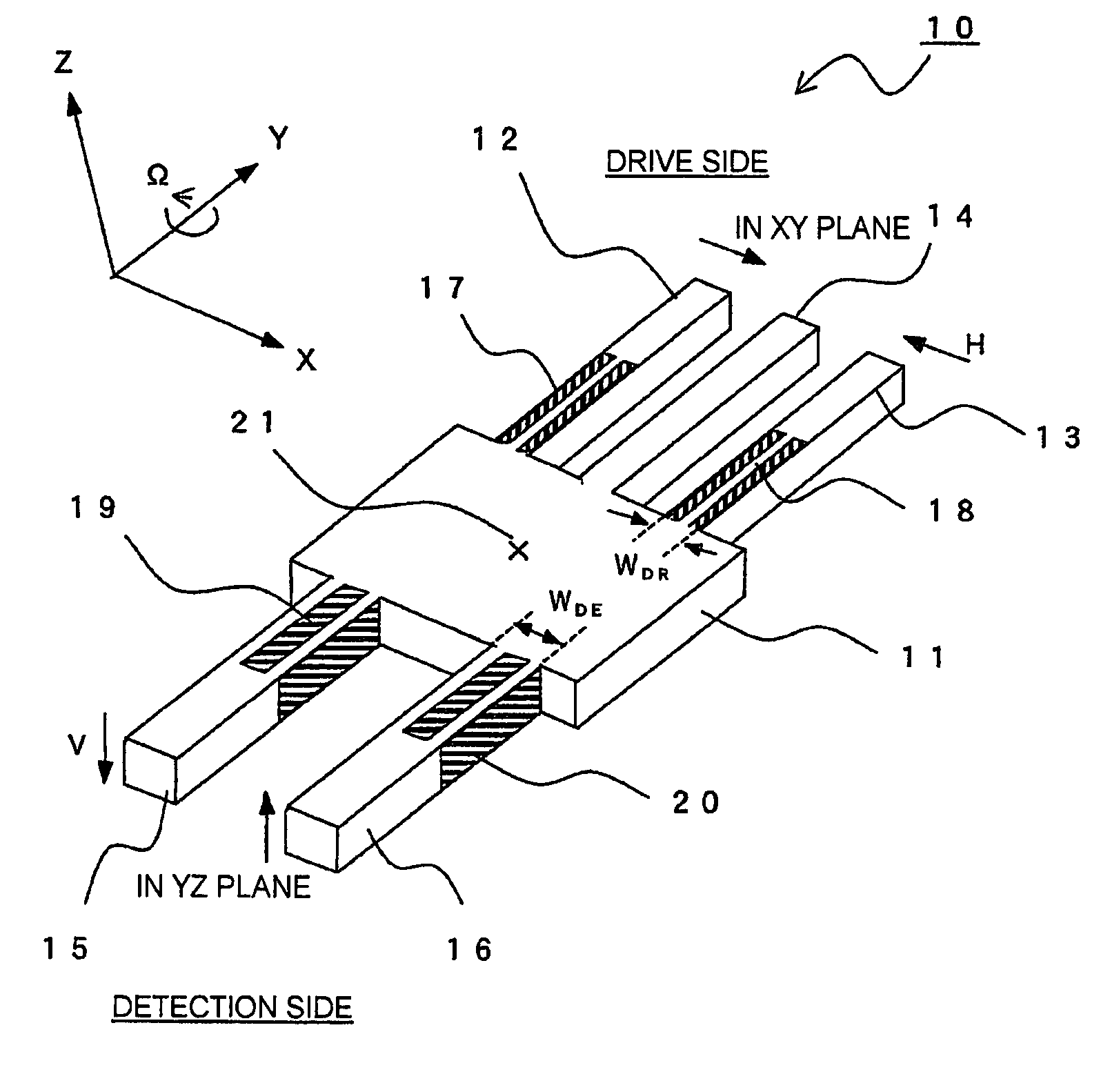
[0038]The vibratory gyroscope shown in FIG. 3 includes a piezoelectric vibrator 10 integrally formed by machining an X-cut langasite wafer. The vibrator 10 is formed from a single flat plate spreading along a reference plane or a principal plane in the form of the XY plane and having a thickness in a thickness direction perpendicular to the principal plane, i.e. in the Z-direction, and has a rectangular body portion 11 at its central portion. The body portion 11 has a geometric center position 21.

[0039]The vibrator 10 further comprises drive arms 12, 13, and 14 and detection arms 15 and 16 extending in mutually opposite directions in the principal plane from the body portion 11. That is, the drive arms 12, 13, and 14 extend parallel to each other in the Y-direction, i.e. a first direction, in the principal plane and the detection arms 15 and 16 extend...

exemplary embodiment 2

[0053]Referring to FIG. 6, a description will be given of a vibratory gyroscope according to exemplary embodiment 2 of this invention.

[0054]The vibratory gyroscope shown in FIG. 6 includes a piezoelectric vibrator 30 formed by applying anisotropic etching to a Z-cut quartz wafer. The vibrator 30 is formed from a single flat plate spreading along a reference plane or a principal plane in the form of the XY plane and having a thickness in a thickness direction perpendicular to the principal plane, i.e. in the Z-direction, and has a rectangular body portion 31 at its central portion. The body portion 31 has a geometric center position 21.

[0055]The vibrator 30 further comprises drive arms 32, 33, and 34 and detection arms 35 and 36 extending in mutually opposite directions in the principal plane from the body portion 31. That is, the drive arms 32, 33, and 34 extend parallel to each other in the Y-direction, i.e. a first direction, in the principal plane and the detection arms 35 and 36...

exemplary embodiment 3

[0067]Referring to FIG. 7, a description will be given of a vibratory gyroscope according to exemplary embodiment 3 of this invention.

[0068]The structure of a vibrator 50 for use in a vibratory gyroscope shown in FIG. 7 is similar to that of the vibrator 10 or 30 shown in FIG. 3 or FIG. 6. In the vibrator 50, only a body portion 51, drive arms 52, 53, and 54, and detection arms 55 and 56 are illustrated, while electrodes for driving and detection are omitted.

[0069]What differs from the vibrator 10 or 30 shown in FIG. 3 or FIG. 6 lies in that a space between width-direction center lines of the exciting drive arms 52 and 53 on the drive side, i.e. an exciting drive arm space SDR, is set greater than a space between width-direction center lines of the detection arms 55 and 56, i.e. a detection arm space SDE.

[0070]As the typical sizes, the body portion 51 has a width of 4 mm and a length of 5 mm, the exciting drive arms 52 and 53 each have a width of 0.4 mm and a length of 6 mm, and the...


PUM


Abstract

A vibratory gyroscope including a vibrator (10) integrally having a plate-like body portion (11) spreading along a reference plane, three drive arms (12, 13, 14) extending in a first direction from the body portion along the reference plane, and two detection arms (15, 16) extending in a second direction opposite to the first direction from the body portion along the reference plane. The three drive arms are composed of two exciting drive arms (12, 13) that are excited in mutually opposite phases in the reference plane and a non-exciting drive arm (14) located between the two exciting drive arms. Each of the three drive arms has an arm width in a width direction along the reference plane and perpendicular to the first direction. Each of the two detection arms has an arm width greater than that of the drive arm in the width direction, thereby suppressing generation of vibrations along the reference plane.

Description

CROSS REFERENCE TO RELATED APPLICATIONS[0001]Applicants claims priority under 35 U.S.C. §119 of Japanese Application No. 2005-006581 filed Jan. 13, 2005. Applicants also claims priority under 35 U.S.C. §365 of PCT / JP2006 / 300564 filed Jan. 11, 2006. The international application under PCT article 21(2) was not published in English.TECHNICAL FIELD[0002]This invention relates to a vibratory gyroscope comprising a vibrator having three drive arms and two detection arms extending in mutually opposite directions from a plate-like body portion.BACKGROUND ART[0003]Generally, vibratory gyroscopes are known as devices for measuring the angular velocity of a rotating object using the fact that a Coriolis force perpendicular to vibration and an angular velocity vector of the rotating object acts on an object vibrating on the rotating object, and have been used as devices for position confirmation in airplanes, large ships, space satellites, and so on. Recently, in the field of consumer products...

Claims


Application Information

Patent Timeline
Patent Type & Authority Patents(United States)
IPC IPC(8): H03H9/21G01C19/56G01C19/5607
CPCG01C19/5607
Inventor OCHI, ATSUSHIINOUE, TAKESHIYAMAMOTO, MITSURUKURAMOTO, KENJINAKAJIMA, MITSUHIROHOSOKAWA, TAKESHITAKAHASHI, HIROYUKINAKAHARA, TAKASHI
Owner JAPAN AVIATION ELECTRONICS IND LTD
Why Eureka
Try Eureka