Method and system for adapting a wireless link to achieve a desired channel quality

a wireless link and channel quality technology, applied in the field of wireless communication systems, can solve the problems of limited wireless frequency bandwidth, large thermal noise at the rf receiver, and large rf bandwidth, and achieve the effect of reducing the rf bandwidth of the uplink communication channel, and reducing the rf bandwidth of the uplink channel

Inactive Publication Date: 2009-05-05
INTEL CORP
View PDF13 Cites 37 Cited by
  • Summary
  • Abstract
  • Description
  • Claims
  • Application Information

AI Technical Summary

Benefits of technology

[0017]A method and system for adapting a wireless communications link between a transmitter and a receiver involves reducing the RF bandwidth of an uplink communications channel to achieve a desired channel quality. The RF bandwidth of the uplink communications channel is reduced when the desired channel quality is not achieved using the entire available RF bandwidth for uplink communications. Reducing the RF bandwidth of an uplink channel enables the uplink limit of a subscriber unit to be extended beyond what is possible when the entire available RF bandwidth is used for uplink communications. In an embodiment, additional uplink time slots are allocated to the uplink communications channel with the reduced RF band so that a constant overall transmission rate can be maintained between the transmitter and the receiver.

Problems solved by technology

Although larger RF bandwidth enables an increased communications rate over a wireless link, the larger RF bandwidth also leads to larger thermal noise at the RF receiver.
Because wireless frequency bandwidth is a limited resource, wireless cellular systems often reuse the same wireless frequencies in different subscriber cells.
Although the reuse of wireless frequencies in different subscriber cells frees up available bandwidth, the reuse of wireless frequencies also causes co-channel interference when signals from one subscriber cell are detected within another subscriber cell.
However, with regard to communications in the uplink direction, from a subscriber unit to a base transceiver station, the channel signal strength, C, is limited by many factors and cannot be easily increased to compensate for an increase in thermal noise.
For example, the channel signal strength of uplink transmissions is limited by power consumption concerns at the subscriber unit (particularly in mobile subscriber units), the cost of high power components (such as power amplifiers and filters), government regulations, and human health concerns.
Because of the limitations in uplink transmission power, the effective size of a wireless subscriber cell is often uplink limited.
The maximum size of the wireless cell in turn effects the capital costs of building a wireless communications system.

Method used


Image

  • Method and system for adapting a wireless link to achieve a desired channel quality
  • Method and system for adapting a wireless link to achieve a desired channel quality
  • Method and system for adapting a wireless link to achieve a desired channel quality

Examples


Embodiment Construction

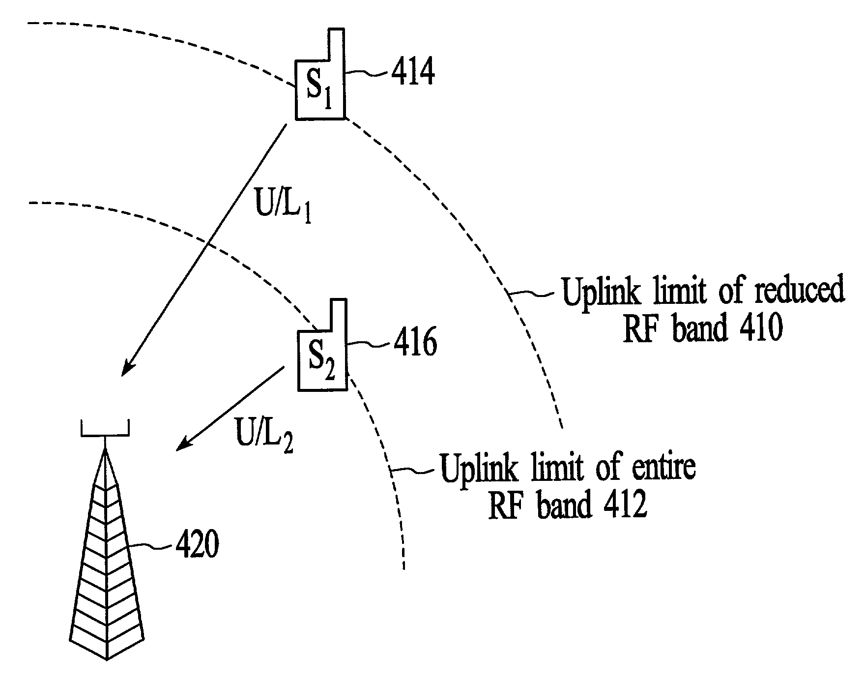
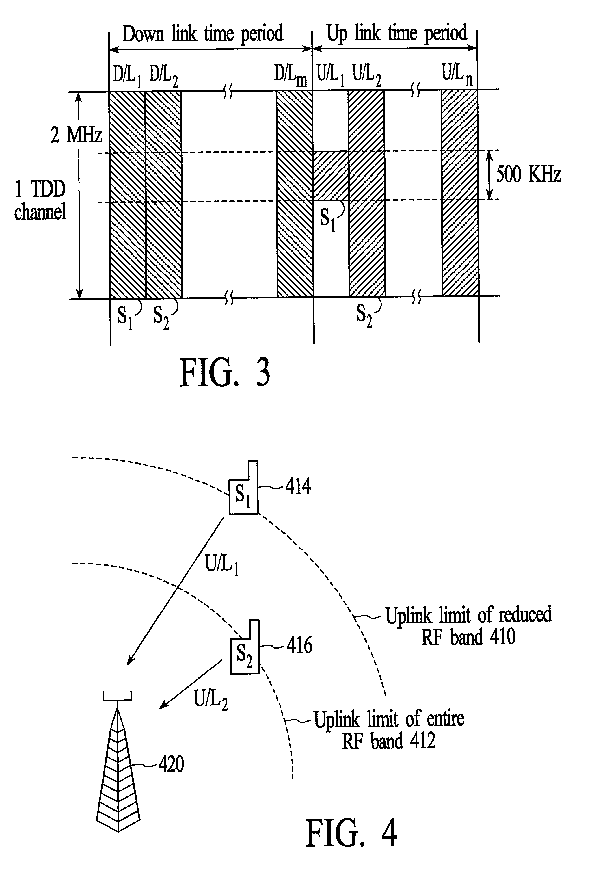
[0038]As shown in the figures for purposes of illustration, the invention is embodied in a system and method for wireless communications that adapts a wireless communications link between a transmitter and a receiver by reducing the RF bandwidth of an uplink communications channel to achieve a desired channel quality. The RF bandwidth of the uplink communications channel is reduced when the desired channel quality is not achieved using the entire available RF bandwidth for uplink communications. Reducing the RF bandwidth of an uplink channel enables the uplink limit of a subscriber unit to be extended beyond what is possible when the entire available RF bandwidth is used for uplink communications.

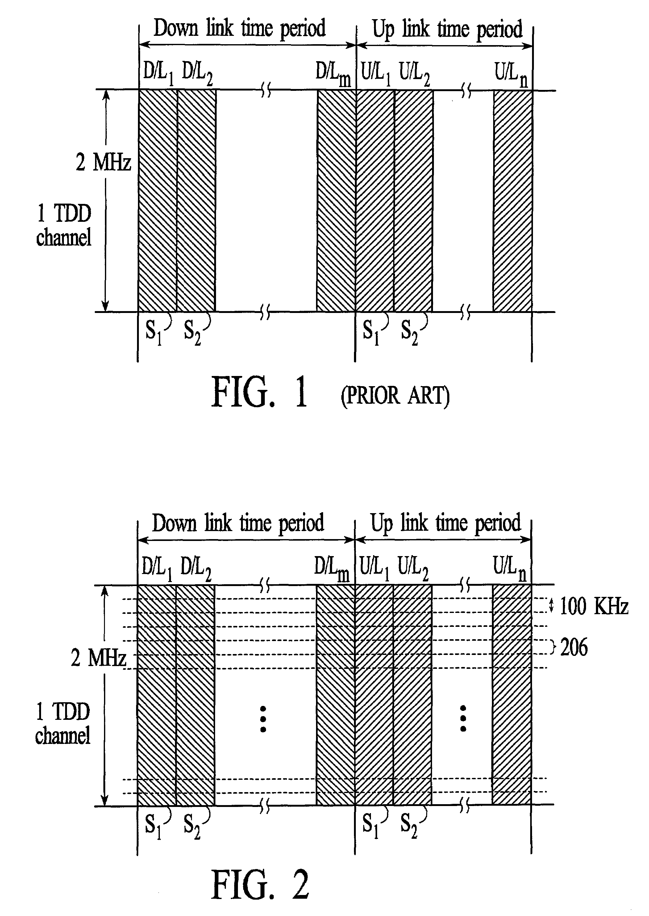
[0039]FIG. 1 depicts the RF bandwidth of an example broadband wireless channel that is utilized between a transmitter and a receiver. In the example of FIG. 1, the channel has an RF bandwidth of 2 MHz that is located in the 2.5 to 2.502 GHz frequency range. As described above, the maximum s...


PUM


Abstract

Adapting a wireless communications link between a transmitter and a receiver involves reducing the RF bandwidth of an uplink communications channel to achieve a desired channel quality. The RF bandwidth of the uplink communications channel is reduced when the desired channel quality is not achieved using the entire available RF bandwidth for uplink communications. Reducing the RF bandwidth of an uplink channel enables the uplink limit of a subscriber unit to be extended beyond what is possible when the entire available RF bandwidth is used for uplink communications. Additional uplink time slots can be allocated to the uplink communications channel with the reduced RF band so that a constant overall transmission rate can be maintained between the transmitter and the receiver.

Description

FIELD OF THE INVENTION[0001]The invention relates generally to wireless communications systems that use multiple access protocols. More particularly, the invention relates to a method and system for adapting a wireless link between a transmitter and receiver pair in a wireless communications system.BACKGROUND OF THE INVENTION[0002]Wireless communications systems use multiple access protocols to enable wireless communications between base transceiver stations and multiple subscriber units. Typically, a wireless communications system includes multiple base transceiver stations that are spaced apart to create subscriber cells. Subscriber units within the subscriber cells exchange information between nearby base transceiver stations over dedicated radio frequencies.[0003]The use of wireless communications systems is rapidly expanding beyond the exchange of voice communications to include the exchange of broadband data, such as multimedia data. For example, a single wireless link between...

Claims


Application Information

Patent Timeline
Patent Type & Authority Patents(United States)
IPC IPC(8): H04W72/00H04L12/56H04W28/20H04W72/04H04W74/04
CPCH04W28/20H04W72/08H04W74/04H04W72/54
Inventor SEBASTIAN, PEROOR K.
Owner INTEL CORP
Why Eureka
Try Eureka