
Device for actively reducing sound transmission, and panel comprising such device

a technology of active reduction and sound transmission, which is applied in the direction of sound producing devices, ear treatment, building components, etc., can solve the problems of relatively heavy, complex and expensive electronics and actuators, and the use of known devices in cases in which relatively little energy is available, so as to reduce the transmission of this sound, reduce the energy consumption of the device according to, and reduce the effect of sound transmission

Inactive Publication Date: 2009-05-12
NEDERLANDSE ORG VOOR TOEGEPAST-NATUURWETENSCHAPPELIJK ONDERZOEK (TNO)
View PDF13 Cites 3 Cited by
  • Summary
  • Abstract
  • Description
  • Claims
  • Application Information

AI Technical Summary

Benefits of technology

[0007]The present invention contemplates a device for actively reducing sound, which device can have a relatively inexpensive and lightweight design and can still effect a desired great sound transmission reduction.
[0009]It has surprisingly been found that, by means of a device whose inner space is provided with at least one inner wall to divide this space into at least two layers of air, which inner wall is arranged such that the layers of air are in fluid connection with each other, a relatively great sound transmission reduction can be effected by means of relatively light, simple and inexpensive electronics and actuators. In addition, the energy consumption of the device according to the invention, at least with a control of the actuators which has been correctly set and / or calibrated for this purpose, has been found to be relatively low. The setting and / or calibration of the actuator control desired for sound transmission reduction can be carried out by a skilled person by means of simple standard measurements and / or an automated feedback system. Here, the device may, for instance, be set up between two test spaces, with sound being produced in one space, while it is detected in the other space to what extent the device has reduced the transmission of this sound with a certain setting of the actuator control. It has been found that, as a result of the relatively simple construction of the device according to the invention, the actuator control can be designed relatively simply, for instance because the control contains a relatively simple mathematical algorithm to control the actuators of the device via control electronics.
[0010]The device provided by the invention can, in itself, have a relatively simple, lightweight and inexpensive design, which is advantageous and desired for various uses. In addition, the device according to the invention can be used with advantage in situations in which relatively little energy is available. In addition, use of the device according to the invention is relatively inexpensive and environment-friendly, due to its low energy consumption. Further, the device according to the invention can have a relatively compact, durable and robust design, so that the device is easily employable in various uses.
[0011]The invention has been found to particularly effect a good reduction of the sound when the first wall is connected to the inner wall by substantially stiff connecting means, while the second wall is connected to the inner wall by flexible connecting means. In this manner, the device comprises a relatively stiff part in which the first layer of air is provided, while the actuators and the second wall can carry out the desired movements for reduction of the sound.

Problems solved by technology

A disadvantage of the known device is that, for a desired good sound transmission reduction, it needs to be provided with relatively heavy, complex and expensive electronics and actuators.
In addition, the known device consumes relatively much energy in order to achieve a desired sound reduction.
Thus, use of the known device in cases in which relatively little energy is available, for instance when the energy is obtained from a battery and / or natural energy sources such as solar and / or wind energy, is not possible or not profitable.
In addition, because of the high energy consumption, the known device is relatively expensive in use.

Method used


Image

  • Device for actively reducing sound transmission, and panel comprising such device
  • Device for actively reducing sound transmission, and panel comprising such device

Examples


Embodiment Construction

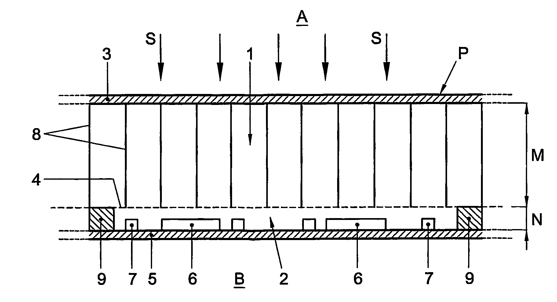
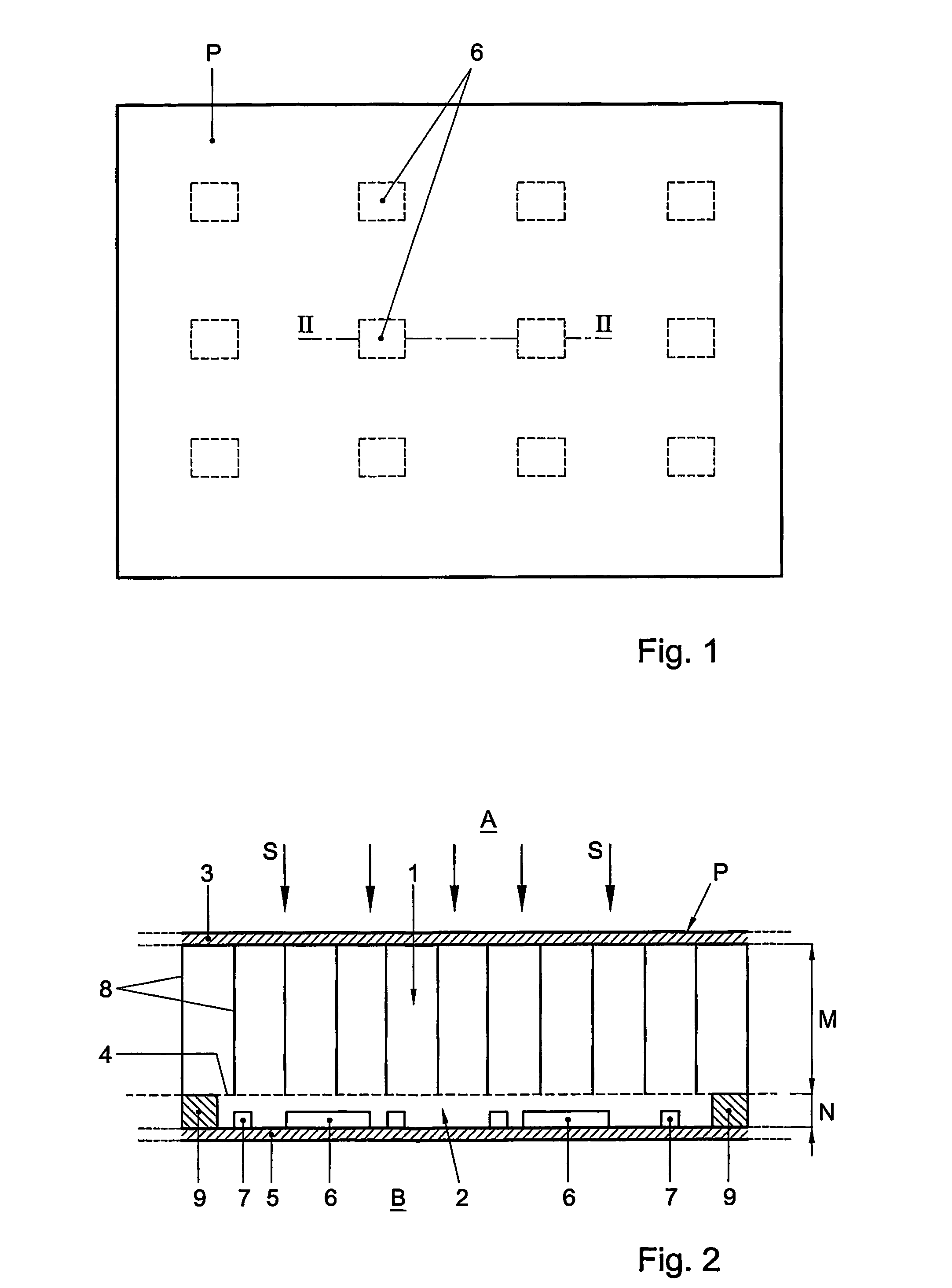
[0016]The device comprises a panel P, provided with a first and a second solid, relatively stiff wall 3, 5 enclosing an inner space. Because the first and second wall 3, 5 have a solid design, this inner space is, at least on longitudinal sides, fluid-tightly closed off from the environment A, B. The inner space is divided into two layers of air 1, 2 by a relatively stiff inner wall 4 set up between the first and second wall 3, 5. In the exemplary embodiment, this inner wall 4, first wall 3, second wall 5 and the layers of air 1, 2 are substantially parallel. The second wall 5 preferably has a lightweight design, for instance in that this wall 5 comprises a relatively thin plate or the like.

[0017]The first wall 3 and the inner wall 4, which enclose the first layer of air 1, are relatively stiffly connected to each other. For this purpose, these walls 3, 4 may, for instance, be coupled to each other via a sandwich structure or a similar relatively open structure. FIG. 2 diagrammatica...


PUM


Abstract

A device for actively reducing sound transmission, provided with a first and second wall (3, 5) enclosing an inner space (1, 2), wherein at least the second wall (5) is provided with actuators (6), for instance eletromagnetic actuators and / or piezoeleteric elements, wherein the said inner space is provided with at least one inner wall (4) to divide this space into at least two layers of air (1, 2), which inner wall (4) is arranged such that the layers of air (1, 2) are in fluid connection with each other.

Description

[0001]This application is the U.S. National Phase of International Application Number PCT / NL2004 / 000102 filed on 11 Feb. 2004, which is incorporated herein by reference.BACKGROUND OF THE INVENTION[0002]The invention relates to a device for actively reducing sound transmission, provided with a first and a second wall enclosing an inner space, wherein at least the second wall is provided with actuators, for instance electromagnetic actuators and / or piezoelectric elements.[0003]Such a device is known from practice, in particular in the form of a sound transmission-reducing panel, and is, for instance, described in international patent application WO94 / 05005. The device may, for instance, be used to reduce disturbing sounds from sound-producing parts of machines, buildings, vehicles, vessels, aircraft and the like. The known device may, for instance, be placed between two spaces in order to actively reduce sound coming from one space such that as little of that sound as possible can rea...

Claims


Application Information

Patent Timeline
Patent Type & Authority Patents(United States)
IPC IPC(8): F01N1/06F01N1/20F01N1/02G10K11/16G10K11/178
CPCG10K11/1788G10K11/17857G10K11/17861G10K2210/3224G10K2210/32291G10K11/178
Inventor BERKHOFF, ARTHUR PERRY
Owner NEDERLANDSE ORG VOOR TOEGEPAST-NATUURWETENSCHAPPELIJK ONDERZOEK (TNO)
Learn More