Device for controlling variable-pitch vanes in a turbomachine

a technology of variable pitch and turbomachine, which is applied in the direction of machines/engines, reaction engines, liquid fuel engines, etc., can solve the problems of significant lack of precision in the angular positioning of the vane about its axis, and achieve the effect of eliminating that drawback, simple, and inexpensiv

Active Publication Date: 2009-05-12
SN DETUDE & DE CONSTR DE MOTEURS DAVIATION S N E C M A
View PDF11 Cites 11 Cited by
  • Summary
  • Abstract
  • Description
  • Claims
  • Application Information

AI Technical Summary

Benefits of technology

[0009]A particular object of the present invention is to eliminate that drawback in a manner that is simple, inexpensive, and effective.
[0011]The device of the invention makes it possible firstly to mount a rod by engaging it in the control ring and on a vane pin by moving the rod in radial translation, because sufficient clearance in the longitudinal direction of the rod is provided for this purpose between the orifice in the rod and the drive square of the blade, and secondly to position the vane angularly in accurate manner about its axis because the clearance is very small or almost zero once the rod is in place on the drive square of the vane.

Problems solved by technology

This clearance is needed during assembly because the drive square is inclined relative to the movement in radial translation of the rod, and after assembly this leads to clearance between the rod and the drive square in the longitudinal direction of the rod, and thus to significant lack of precision in the angular positioning of the vane about its axis.

Method used


Image

  • Device for controlling variable-pitch vanes in a turbomachine
  • Device for controlling variable-pitch vanes in a turbomachine
  • Device for controlling variable-pitch vanes in a turbomachine

Examples


Embodiment Construction

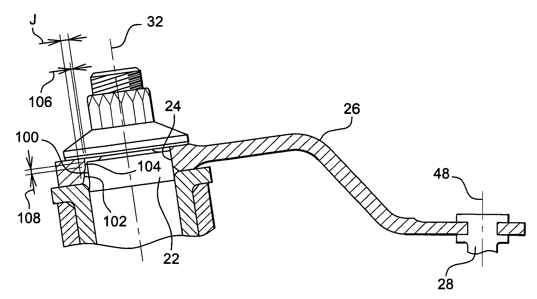
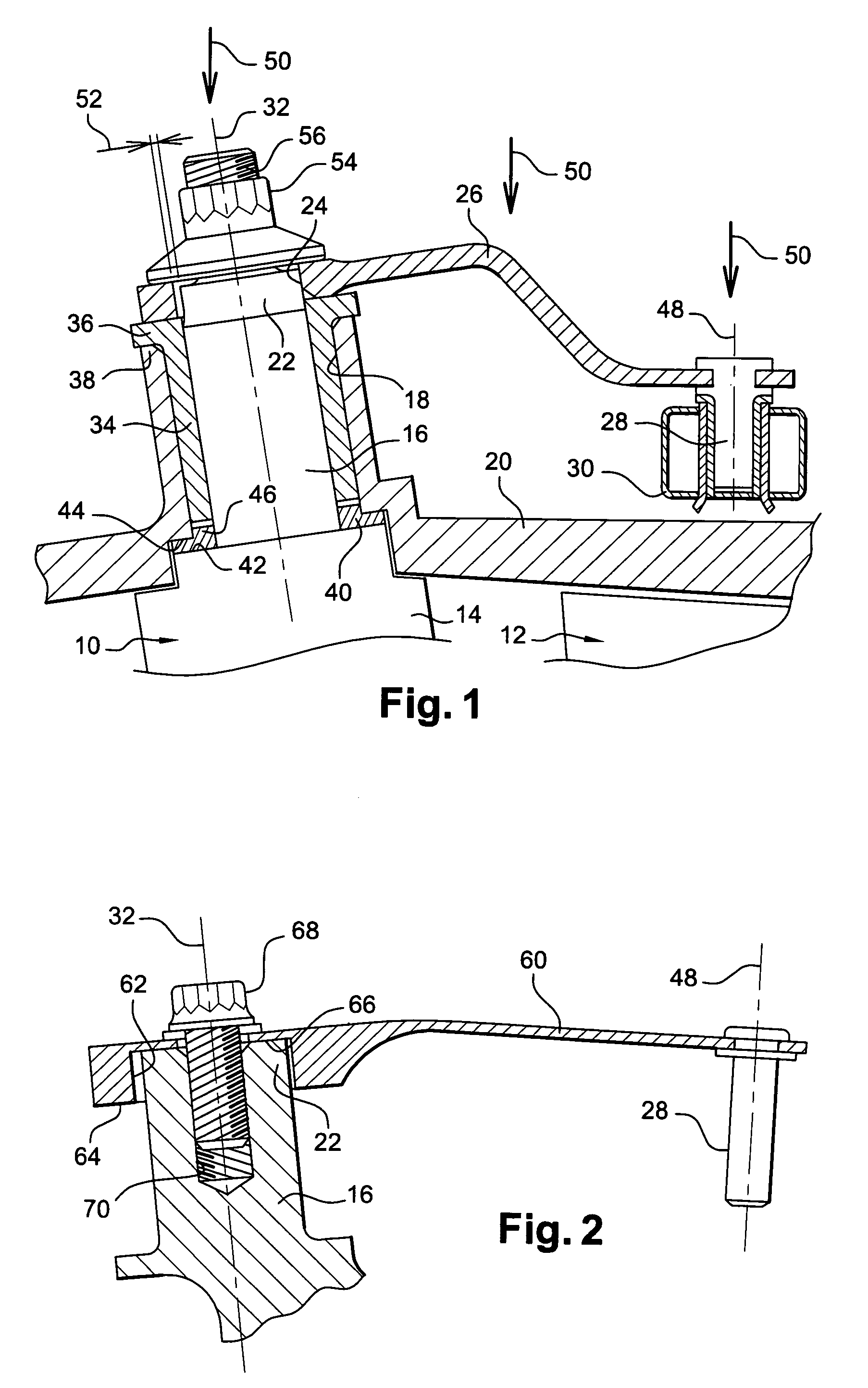
[0024]FIG. 1 is a diagrammatic axial section view of a portion of a variable-pitch vane for a high-pressure compressor of a turbomachine, in particular an airplane turboprop or turbojet, the compressor comprising stationary vane stages 10 for straightening out the flow of the gas stream through the compressor, alternating with moving blade stages 12 carried by the rotor of the compressor.

[0025]Each stator vane 10 comprises an airfoil 14 and a radially outer cylindrical pin 16 mounted in a cylindrical passage 18 of a casing 20 of the compressor and shaped at its radially outer end with a drive square 22 having engaged thereon a corresponding orifice 24 made in one end of a control rod 26.

[0026]The other end of the rod 26 carries a radial cylindrical finger 28 for assembly in a control ring 30 which surrounds the outside of the casing 20 and which is associated with actuator means (not shown) serving to cause it to turn in one direction or the other about the axis of the turbomachine ...


PUM


Abstract

A device for controlling variable-pitch vanes in a turbomachine has rods each having at one end a finger for mounting in a control ring and at its other end an assembly orifice for mounting on a drive square of a vane, the axis of the vane being inclined relative to the axis of the finger of the rod, and the assembly orifice in the rod presenting a dimension in the longitudinal direction of the rod that is greater than that of the drive square, and co-operating therewith to define clearance that varies over the height of the drive square and of the orifice.

Description

[0001]The invention relates to a device for controlling variable-pitch vanes in a turbomachine, such as an airplane turbojet, for example.BACKGROUND OF THE INVENTION[0002]In a turbojet, stages of vanes are mounted between stages of compressor or turbine wheels in order to straighten out the flow of the stream. These vanes are carried by the stator and they are adjustable in pitch position about their respective axes in order to optimize the flow of gas through the nozzles they constitute.[0003]Each stator vane, or variable-pitch vane, includes a cylindrical pin for guiding it in pivoting, the pin being mounted in a cylindrical passage in the casing of the turbojet and being terminated by a drive square having engaged thereon a complementary orifice formed at one end of a rod. The other end of the rod carries a radial cylindrical finger for mounting in a control ring which surrounds the outside of the casing and which is connected to means for turning it about the axis of the turboje...

Claims


Application Information

Patent Timeline
Patent Type & Authority Patents(United States)
IPC IPC(8): F03B3/18
CPCF01D17/16F01D17/162F04D29/563F05D2230/60
Inventor RIBASSIN, FRANCOIS PIERRE GEORGES MAURICERAULIN, DOMINIQUE
Owner SN DETUDE & DE CONSTR DE MOTEURS DAVIATION S N E C M A
Why Eureka
Try Eureka