Controller for servomotor

a technology for servomotors and controllers, applied in the direction of electric controllers, program control, instruments, etc., can solve the problems of lowering the surface affecting and unable to achieve the intended shape, so as to prevent the lowering of the quality of machined parts

Active Publication Date: 2009-05-12
FANUC LTD
View PDF18 Cites 10 Cited by
  • Summary
  • Abstract
  • Description
  • Claims
  • Application Information

AI Technical Summary

Benefits of technology

[0010]The present invention provides a controller capable of selectively switching performing / non-performing of correction to a position command, position deviation or velocity command in accordance with conditions and occasions. The invention also provides a controller capable of reducing a shock caused by variation of the position command or velocity command depending on whether the correction amount is null or not at the time the correction starts or ends.
[0012]According to another aspect of the present invention, the controller comprises: detecting means for detecting a magnitude of a fluctuation factor of the controlled object; correcting means for correcting one of the position command, the position deviation and the velocity command by a correction amount; determining means for determining and updating the correction amount based on the magnitude of the fluctuation factor detected by the detecting means during the control of the servomotor; and switching means for selectively suspending / resuming the updating of the correction amount by the determining means according to an external signal. With this arrangement, the switching can be made between performing the correcting of one of the position command, the position deviation and the velocity command by the correction amount updated in accordance with the fluctuation factor in view of accurate and quick positioning, and suspending the updating of the correction amount to perform the correction with the fixed correction amount in view of quality of a machined surface, so that a sharp change of the correction amount is prevented in the switching not to impart a shock to the machine.
[0018]Since the switching between performing and non-performing of correction of the position command, the position deviation or the velocity command by the correction amount determined based on the fluctuation factor of the controlled object, or the switching between correction by the updated correction amount and correction by the fixed correction amount is made in accordance with an external signal, the control for carrying out accurate and quick positioning and the control of preventing lowering of quality of a machined surface possibly caused by variation of the correction amount is selected in accordance with conditions and occasions.

Problems solved by technology

Thus, if the feed mechanism undergoes thermal displacement, even when the servomotor is driven correctly according to the machining program, the intended shape cannot be achieved due to this thermal displacement, or in other words, the machining accuracy lowers.
In the machine tool, when the correction amount used for correcting a position command, position deviation or velocity command varies during machining, such variation leads to fluctuation of the position of the servomotor, and causes lowering of the surface quality of a machined piece.
Further, if correction to a position command, position deviation or velocity command is not carried out, the position of an object becomes different from the position designated by a command due to thermal displacement or the like as mentioned above, which results in a greater positioning error.

Method used


Image

  • Controller for servomotor
  • Controller for servomotor
  • Controller for servomotor

Examples


first embodiment

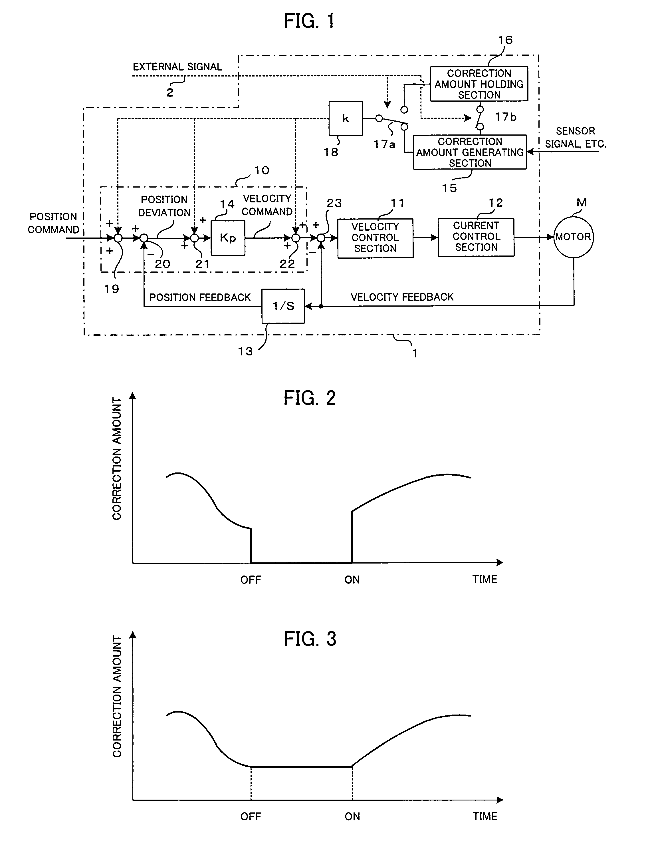
[0026]FIG. 1 is a schematic block diagram showing the present invention.

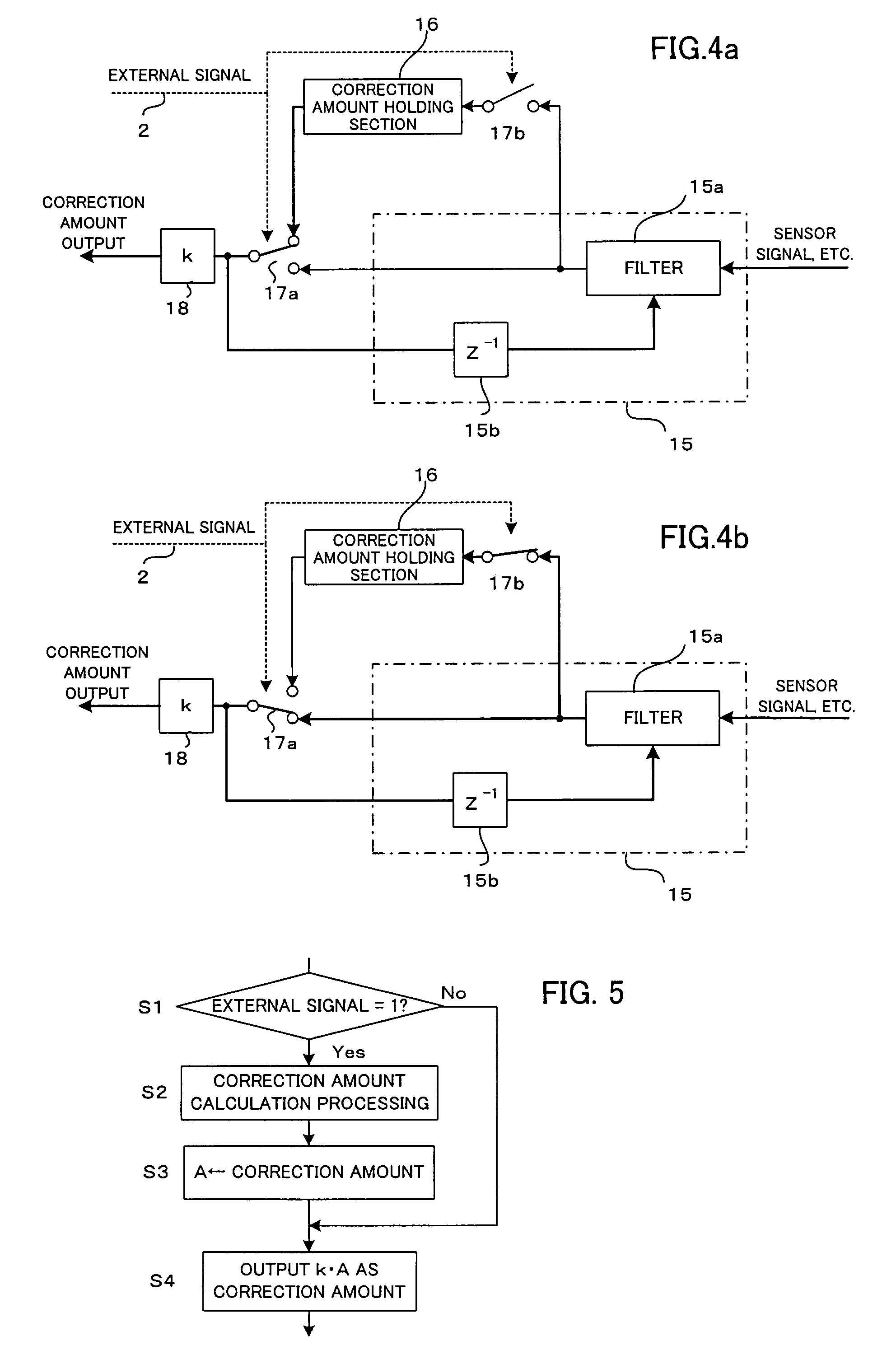
[0027]Like the prior servomotor controllers, a servomotor controller 1 has a position control section 10, a velocity control section 11 and a current control section 12, and as the elements relating to the present invention, also has a correction amount generating section 15, a correction amount holding section 16, selector switches 17a, 17b operating in an associated manner, and a coefficient section 18.

[0028]In the position control section 10, a velocity command is obtained as follows: A position feedback is obtained by integrating means 13 performing integration of velocity feedbacks from a velocity detector such as a pulse encoder provided to a servomotor M; then, a position deviation is obtained by a subtractor 20 subtracting the position feedback from a position command outputted from a host controller such as a numerical controller; and then, by multiplying the position deviation by a position gain Kp as ...

second embodiment

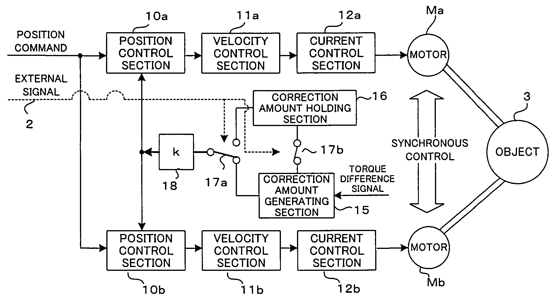
[0051]FIG. 6 is a schematic block diagram showing the present invention.

[0052]The second embodiment is an embodiment of a controller designed to perform a tandem control in which one object 3 is driven by two servomotors Ma, Mb subjected to synchronous control.

[0053]It is arranged such that an object 3 is driven by two servomotors Ma, Mb. As means for drive-controlling the servomotors Ma, Mb individually, position control sections 10a, 10b, velocity control sections 11a, 11b and current control sections 12a, 12b are provided. The position control sections 10a, 10b each send out a velocity command through position feedback control as shown in FIG. 1, based on a motion command outputted from a host controller such as a numerical controller and a position feedback from a position detector provided to each of the servomotors Ma, Mb or a position detector provided for detecting the position of the object 3. It is to be noted that from the host controller, the same position command is out...


PUM


Abstract

A controller for a servomotor capable of improving accuracy of positioning and quality of a machined surface by switching modes of correction of a position command or the like, and reducing a shock at the time of switching. A correction amount generating section obtains a correction amount based on a value of a correction factor such as machine temperature. When the external signal is in ON state, a position command or the like is corrected by the correction amount obtained by the correction amount generating section and sent via switches. A correction amount holding section holds the correction amount obtained by the correction amount generating section. When the external signal turns to OFF state, the connection of the switches is changed so that correction is performed by the correction amount held in the correction amount holding section. When the connection of the switches is changed, the correction amount does not change rapidly, so that the machine does not suffer a shock. In positioning, the external signal is turns to ON state, so that the positioning is carried out accurately by performing correction by the correction amount sent from the correction amount generating section. When a high-quality machined surface is required, the external signal is turned to OFF state so that the correction amount does not change to achieve improvement in the quality of a machined surface.

Description

BACKGROUND OF THE INVENTION[0001]1. Field of the Invention[0002]The present invention relates to a controller for controlling a servomotor for use as a driving source of a movable part of a machine such as a machine tool, so as to control position and / or velocity of the movable part of the machine.[0003]2. Description of Related Art[0004]In machine tools, a servomotor is used as a driving source for a feed axis which moves a movable part such as a tool or a table with a workpiece mounted on, where by driving the feed axis by controlling the position and velocity of the servomotor, the workpiece is machined into a shape designated by a machining program or the like.[0005]Regarding the controlling of such servomotor, there is known a method in which a position command or a velocity command is corrected so that a workpiece can be machined into a designated shape with high accuracy. When the machine continues to be used, the machine is heated by heat produced from the motor, etc. and un...

Claims


Application Information

Patent Timeline
Patent Type & Authority Patents(United States)
IPC IPC(8): G05B11/32H02P29/02
CPCG05B19/404
Inventor IWASHITA, YASUSUKEOKITA, TADASHIKAWAMURA, HIROYUKITAKAYAMA, KENICHI
Owner FANUC LTD
Why Eureka
Try Eureka