Distributed radio frequency ranging signal receiver for navigation or position determination

a radio frequency ranging and receiver technology, applied in direction finders, direction finders using radio waves, instruments, etc., can solve the problem that the accuracy of the suedolite system may be limited to several meters, and achieve the effect of increasing the dynamic range, and reducing the cost of operation

Active Publication Date: 2009-05-12
TRIMBLE NAVIGATION LTD
View PDF123 Cites 24 Cited by
  • Summary
  • Abstract
  • Description
  • Claims
  • Application Information

AI Technical Summary

Benefits of technology

[0005]The present invention is defined by the following claims, and nothing in this section should be taken as a limitation on those claims. By way of introduction, the preferred embodiments described below include methods and systems for a land-based range or position determination. To provide sub-meter accuracy, ranging signals with a high modulation rate of code, such as 30 MHz or more, are transmitted. Code phase measurements may be used to obtain the accuracy without requiring relative motion or real time kinematic processing to resolve any carrier cycle ambiguity. The ISM bands or X-band is used for the carrier of the code to provide sufficient bandwidth within available spectrums. The length of codes used is at least about a longest length across the region of operation, yet less than an order of magnitude longer, such as about 15 kilometers in an open pit mine, but other lengths may be used. The spread spectrum codes from different land-based transmitters are transmitted in time slots pursuant to a time division multiple access scheme for an increase in dynamic range. The dynamic range is a range of power over which a receiver can track a signal, to distinguish from “range” as in distance measurement. To avoid overlapping of code from different transmitters, each time slot includes or is separated by a blanking period. The blanking period is selected to allow the transmitted signal to traverse a region of operation without overlap with a signal transmitted in a subsequent time slot by a different transmitter. Differential measurements of signals received at a base station and a mobile receiver may allow for improved accuracy. Any one or more of the signal structure characteristics summarized above may be used independently or in combination with other signal characteristics in a land-based transmitter system.
[0006]In addition to or for use independently of the signal structure characteristics discussed above, the land-based transmitters include free running oscillators or oscillators free of clock synchronization with any remote oscillator. A reference receiver receives the ranging signals from different transmitters and generates timing offset information, such as code phase measurements. The timing offset information is then communicated back to transmitters. The temporal offset information indicates relative timing or phasing of the different transmitted ranging signals to the reference receiver. The transmitters then transmit the temporal offset information with the ranging signals, such as modulating the transmitted code by the timing offset information. A mobile receiver is operable to receive the ranging signals and timing offset information in a same communications path, such as on a same carrier. Alternatively, the timing offset information is communicated from the reference directly to the mobile. A system with oscillators that are synchronized with GNSS or any other synchronization source may be used. Position is determined with the temporal offset information and the ranging signals. The temporal offset information for the various transmitters allows the mobile receiver to more accurately determine position than in an unsynchronized system. Various aspects of the synchronization of the system discussed above may be used independently of each other or in combination.

Problems solved by technology

As a result of using GNSS types of signals, psuedolite systems may be limited to several meters of accuracy based on code phase measurements.

Method used


Image

  • Distributed radio frequency ranging signal receiver for navigation or position determination
  • Distributed radio frequency ranging signal receiver for navigation or position determination
  • Distributed radio frequency ranging signal receiver for navigation or position determination

Examples


Embodiment Construction

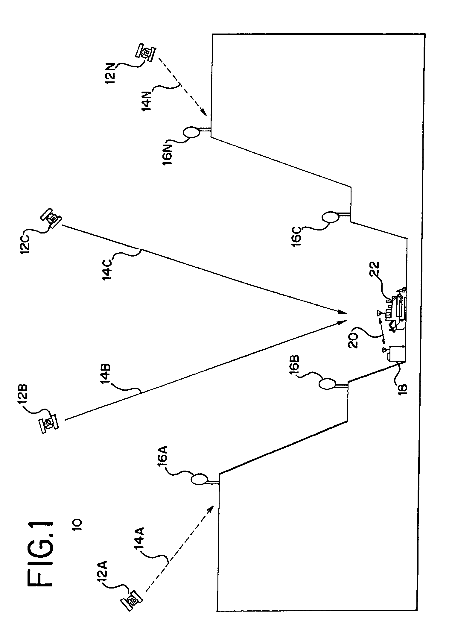
[0037]GNSS relies on access to a plurality of satellites at any given location on the globe. For example, access to at least five satellites allows for position solution with carrier phase based centimeter accuracy. Some locations lack sufficient access to satellites. For example, FIG. 1 shows a system 10 with a plurality of satellites 12A-N relative to an open pit mine. A reference station 18 and mobile receiver 22 have lines of sight 14B, 14C to two satellites 12B, 12C but the walls of the mine block access to signals from other satellites 12A, 12N. In order to provide accurate positioning, a plurality of land-based transmitters 16A-N are positioned within, encircling, around, or combination thereof the mine.

[0038]The land-based transmitters 16, reference station 18 and / or mobile receiver 22 are a local positioning system. The local positioning system is operable without the satellites 12, but may be augmented with the satellites 12. Additional, different or fewer components may b...


PUM


Abstract

In a local positioning system, a receiver is adapted for receiving signals from a land-based transmitter. The receiver includes an analog decorrelator for decorrelating the transmitted spread spectrum signals. A down converter connected with an antenna may be spaced away from other portions of the receiver. The down converter down converts received ranging signals and provides them to the remotely spaced receiver portions. A signal line connecting the down converter to the receiver may be operable to transmit any two or more of a reference signal provided to the down converter, the down converted intermediate frequency signals provided to the receiver, and power provided to the down converter. The receiver may be positioned adjacent to or as part of a land-based transmitter. By determining positions of two or more antennas, the location of the associated transmitter is determined.

Description

BACKGROUND[0001]The present invention relates to range or position determination. In particular, signal structures, transmitters, receivers, other components and / or methods of operation of a ranging or positioning system are provided.[0002]Global navigation satellite systems (GNSS) allow a receiver to determine a position from ranging signals received from a plurality of satellites. Different GNSS systems are available or have been proposed, such as the global positioning system (GPS), Gallileo or GLONASS. The GPS has both civilian and military applications. Different ranging signals are used for the two different applications, allowing for different accuracies in position determination.[0003]Position is determined from code and / or carrier phase information. A code division multiple access code is transmitted from each of the satellites of the global positioning system. The spread spectrum code is provided at a 1 MHz modulation rate for civilian applications and a 10 MHz modulation ...

Claims


Application Information

Patent Timeline
Patent Type & Authority Patents(United States)
IPC IPC(8): G01S3/02G01S1/00G01S19/44G01S19/46
CPCG01S19/11G01S19/44G01S19/46G01S19/55G01S19/32
Inventor ZIMMERMAN, KURT R.BAUREGGER, FRANK N.
Owner TRIMBLE NAVIGATION LTD
Why Eureka
Try Eureka