Unmanned underwater vessel

a technology for underwater vessels and motors, applied in underwater equipment, special-purpose vessels, vessel construction, etc., can solve the problem of superfluous adaptation of the closed-loop control circuit of the drive assembly to a new trim

Active Publication Date: 2009-05-19
ATLAS ELEKTRONIC GMBH
View PDF6 Cites 10 Cited by
  • Summary
  • Abstract
  • Description
  • Claims
  • Application Information

AI Technical Summary

Benefits of technology

[0009]In the same way as the attachment of the underwater antennas and the propeller protection apparatuses, it is also possible to attach further ancillary devices, which impart additional functions to the underwater vessel. For example, a TV camera can be inserted into that end of a drive tube which faces away from the propeller. The holder of a load-bearing frame, with which the underwater vessel can accomm

Problems solved by technology

This not only means savings in terms of repeated trim calculations and trim tests for the converted underwater vessel but al

Method used


Image

  • Unmanned underwater vessel
  • Unmanned underwater vessel
  • Unmanned underwater vessel

Examples


Embodiment Construction

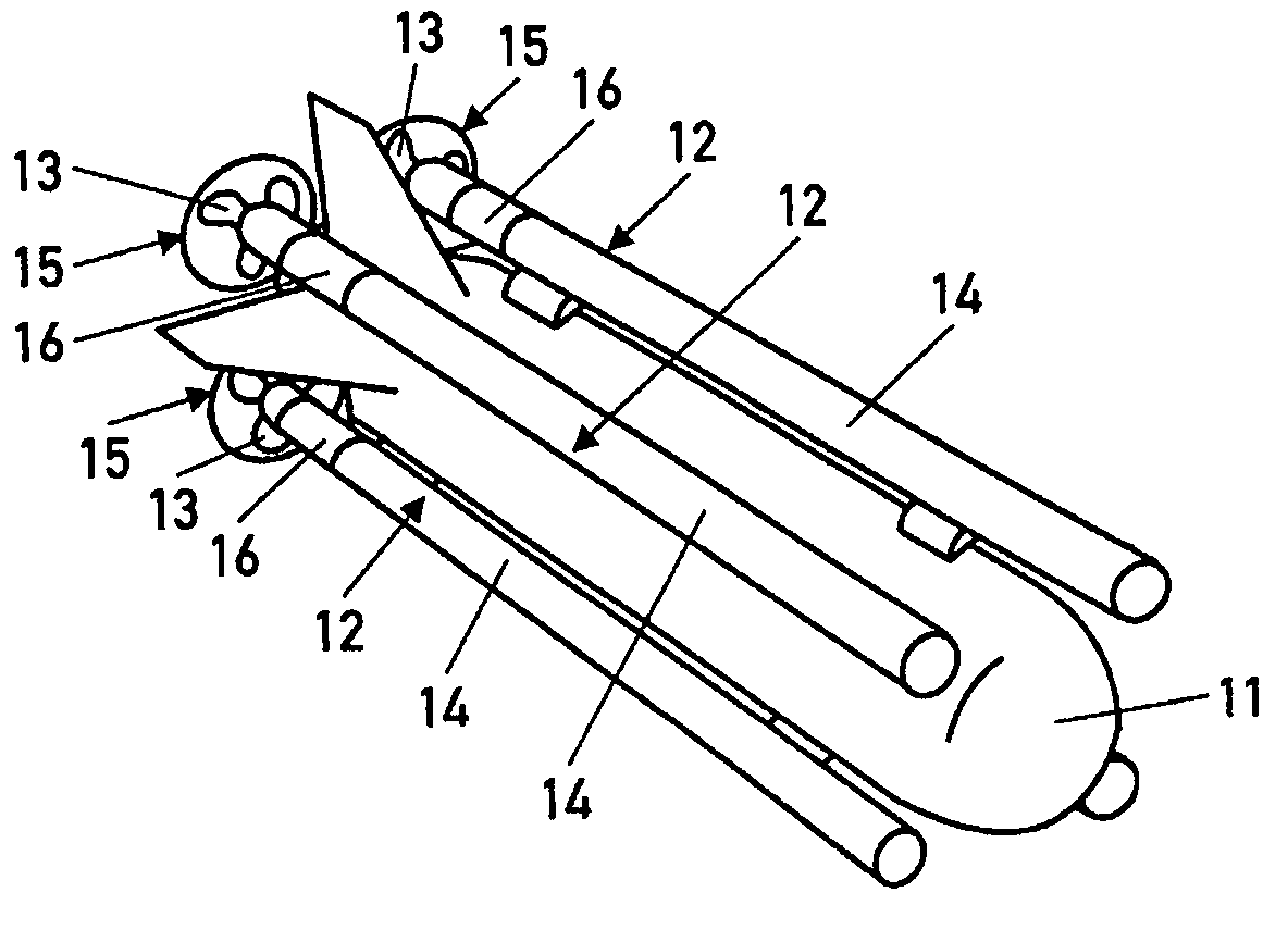
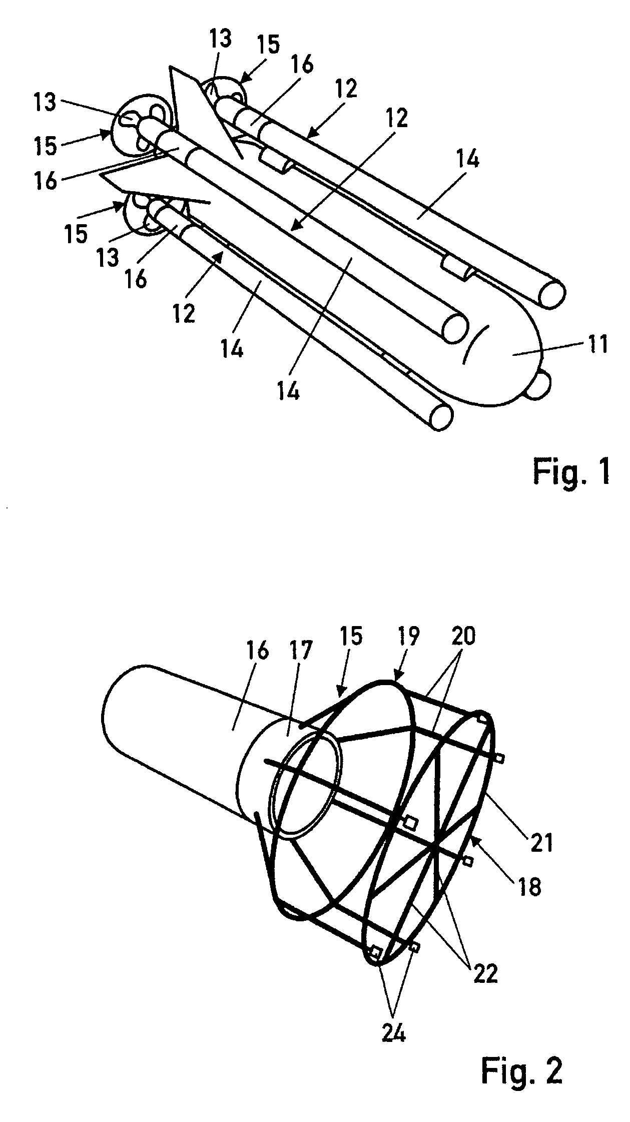
[0016]The unmanned underwater vessel, which is illustrated in a perspective view in FIG. 1, has a pressure hull 11 and a drive assembly comprising in total four propeller drives 12. Of the propeller drives 12, two are arranged on or close to the upper side of the pressure hull 11 and two on or close to the underside of the pressure hull 11, in each case on the starboard and port side of the pressure hull 11. Each propeller drive 12 has an electric motor, which drives a propeller 13 via a drive shaft. The electric motor and the drive shaft are accommodated in each case one drive tube 14 fixed to the pressure hull 11, the drive shaft being mounted such that it can rotate in the drive tube 14. The propeller 13 is placed onto that end of the drive shaft which protrudes out of the drive tube 14. Each propeller 13 is provided with a protection apparatus 15, which protects the propeller 13 against damage on contact with the ground, on contact with the wall of a vessel or by flotsam and jet...


PUM


Abstract

With an unmanned underwater vessel having a pressure hull, drive assembly and at least one ancillary device arranged on the pressure hull, for example a propeller protection apparatus (15), the at least one ancillary device (15) is fixedly connected to a lifting body (16), which has a lower density than the density of the water, in order to make it possible to replace the ancillary devices or to arrange additional ancillary devices on the pressure hull without changing the trim of the underwater vessel as a result. The density and volume of the lifting body (16) are selected such that the lifting force acting in the water on the ancillary device (15) and the lifting body (16) compensates for the force of gravity acting on the ancillary device (15) and the lifting body (16).

Description

BACKGROUND OF THE INVENTION[0001]The invention relates to an unmanned underwater vessel of the generic type having a pressure hull, a drive assembly, and at least one ancillary device arranged on the pressure hull.[0002]Self-driven, preferably propeller-driven, unmanned underwater vessels are used as autonomously operating vessels or as vessels which are remote-controlled via a data transmission cable for the purpose of carrying out various tasks under water, so-called missions, such as for reconnaissance work on the topography of the seabed, for clearing mines and the destruction of mines. In this case, similarly designed vessels are equipped with different devices and components, depending on the profile of requirements, and these devices and components are arranged in various regions on the pressure hull of the vessels. The vessel, which is equipped in accordance with a specific profile of requirements, is trimmed individually, such that it has an almost horizontal alignment in t...

Claims


Application Information

Patent Timeline
IPC IPC(8): B63G8/08B63G8/00B63G8/24B63G8/26B63H5/16
CPCB63G8/001B63G8/24B63G8/26B63H5/165
Inventor LAMBERTUS, DETLEFRICHTER, RALF
Owner ATLAS ELEKTRONIC GMBH
Why Eureka
Try Eureka