Al technical title is built by PatSnap Al team. It summarizes the technical point description of the patent document.
a technology for transferring beds and hospital beds, which is applied in the direction of nursing beds, transportation and packaging, transportation items, etc., can solve the problems of increasing hospital expenses, affecting the efficiency of hospital beds, so as to achieve the effect of reducing the footprint area of the machin
Inactive Publication Date: 2009-05-19
DANE INDS
View PDF107 Cites 27 Cited by
Summary
Abstract
Description
Claims
Application Information
AI Technical Summary
This helps you quickly interpret patents by identifying the three key elements:
Problems solved by technology
Method used
Benefits of technology
[0007]The present invention, in one embodiment, is a bed transfer system comprising a base portion, an attachment portion, an elevator mechanism, a motor controller and a steering controller. In one embodiment, the base portion comprises a wheel assembly, a steering assembly, a support castor, a locking mechanism, a hinged panel and a power supply. The wheel assembly is pivotally coupled about a first vertical axis to the base portion and includes a drive wheel and a first electric motor mounted in a hub of the drive wheel. The steering assembly includes a second electric motor and a mechanical arrangement for causing the wheel assembly to pivot about the first vertical axis. The support castor is pivotally coupled about a second vertical axis to the base portion. The locking mechanism is adapted to engage the support castor to prevent the support castor from pivoting about the second vertical axis. The hinged panel pivots outwardly from the base portion to facilitate pivoting of the wheel assembly about the first vertical axis. The power supply provides power to the first and second motors.
Problems solved by technology
As a result, a significant number of injuries occur each year to people who move hospital beds.
This pushing requires the person to use the legs, hips, back, arms, and hands, any one of which is susceptible to injury from over exertion.
These injuries cause lost work time and long-term health problems for people who move hospital beds, and they cause added expenses to the hospitals.
And lastly, the people that must move the beds are often nurses, and moving hospital beds contributes to the already high rate of nurse workplace injuries and is typically not a task the nurses enjoy.
Method used
Image
Click on the blue label to locate the original text in one second.
Reading with bidirectional positioning of images and text.
Examples
first embodiment
a. First Embodiment of the Hospital Bed Transfer System
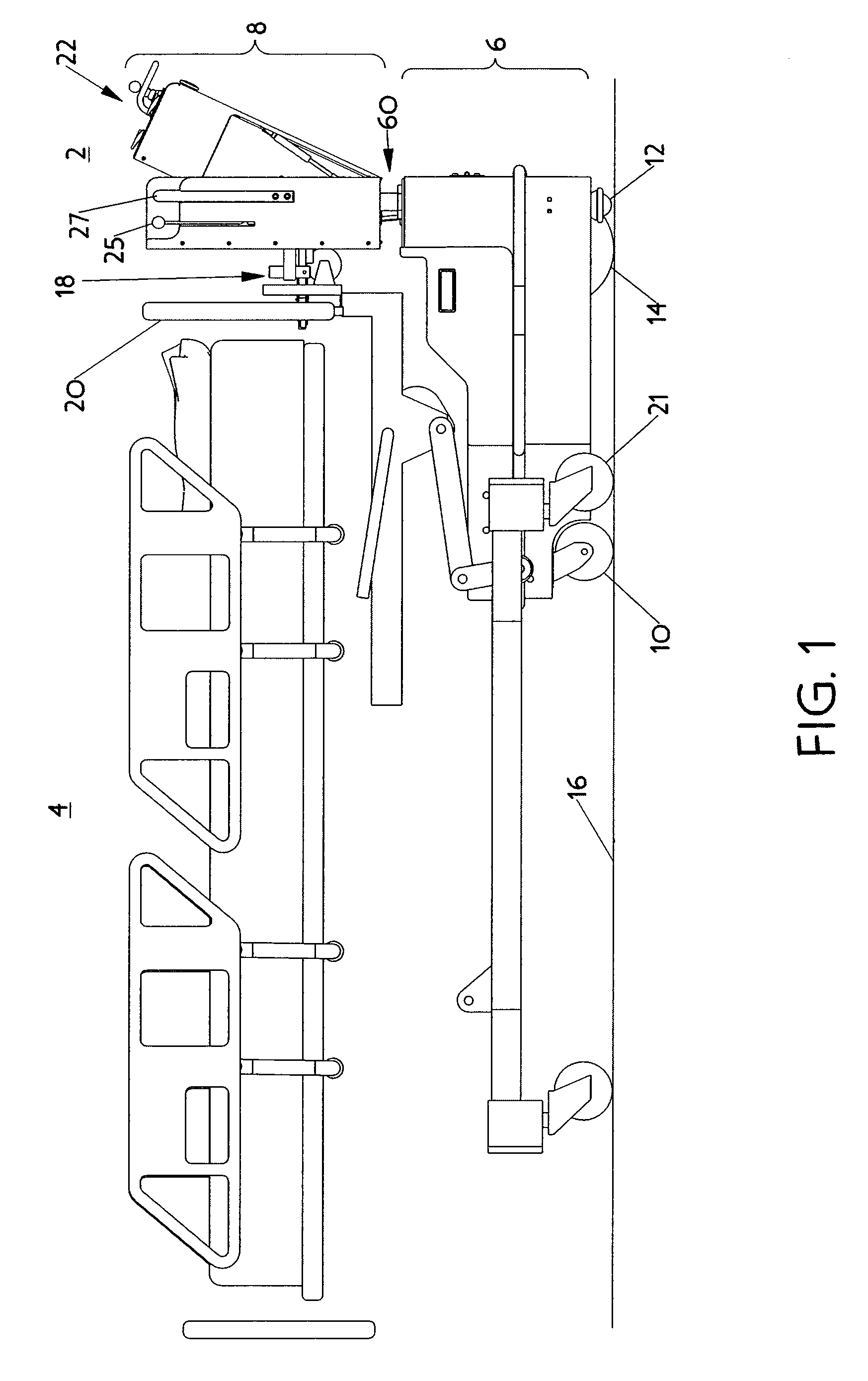
[0066]The present invention, in a first embodiment, is a hospital bed transfer system 2 or powered hospital bed mover for transferring a hospital bed 4 from one location to another in a medical facility. As shown in FIG. 1, which is a side elevation of the first embodiment of the bed mover 2 engaged with a hospital bed 4, the bed mover 2 includes a base portion 6 and an attachment portion 8 extending upward from the base portion 6.
[0067]As illustrated in FIG. 1, the base portion 6 includes a pair of support castors 10 near the frontmost part of the base portion 6, a pair of stabilization castors 12 near the rearmost part of the base portion 6, and a drive wheel 14 located near the rearward part of the base portion 6. The drive wheel 14 and the support castors 10 support the mover 2 off of a travel surface 16 such as a medical facility floor. The drive wheel 14 also powers the mover 2 along the travel surface 16. As indicated in ...
PUM
Abstract
The present invention is a powered hospital bed mover or bed transfer system. The bed mover includes a bed attachment mechanism that is vertically displaceable relative to a base that includes an electrically powered drive wheel and a pair of support castors. The attachment mechanism includes a pair of horizontally oriented jaws with jaw openings that face away from each other. Each jaw includes a contact switch in its bottom surface and a contact switch in its jaw opening. The contact switches indicate to the mover and its user that the mover is properly engaged with the frame of a hospital bed. The jaws are horizontally displaceable and diverge from each other to engage vertical frame members of a hospital bed. A control panel has a joystick adapted to control the speed and direction of travel for the mover. The control panel also has controls for actuating the jaws, changing the elevation of the attachment mechanism, and locking at least one of the support castors. The control panel is hinged to the mover such that it may pivot outwardly away from the mover. A hinged panel also is provided to allow the pivoting of the drive wheel about a vertical pivot axis.
Description
CROSS-REFERENCE TO RELATED APPLICATIONS[0001]The present application claims priority to U.S. Provisional Patent Application 60 / 621,357, which was filed Oct. 22, 2004. Also, the present application claims priority to, and is a continuation-in-part (“CIP”) of, U.S. patent application Ser. No. 11 / 017,975, which was filed Dec. 21, 2004 and is a continuation of U.S. patent application Ser. No. 10 / 280,157, which was filed Oct. 25, 2002 and issued Mar. 29, 2005 as U.S. Pat. No. 6,871,714, which claims priority to U.S. Provisional Patent Application 60 / 336,352, which was filed on Oct. 26, 2001. The present application also claims priority to, and is a continuation-in-part (“CIP”) of, U.S. patent application Ser. No. 10 / 836,593, which was filed Apr. 30, 2004 and claims priority to U.S. Provisional Patent Application 60 / 467,441, which was filed May 3, 2003. All of the aforementioned patent applications are hereby incorporated by reference in their entireties into the present application.FIELD...
Claims
Application Information
Patent Timeline
Application Date:The date an application was filed.
Publication Date:The date a patent or application was officially published.
First Publication Date:The earliest publication date of a patent with the same application number.
Issue Date:Publication date of the patent grant document.
PCT Entry Date:The Entry date of PCT National Phase.
Estimated Expiry Date:The statutory expiry date of a patent right according to the Patent Law, and it is the longest term of protection that the patent right can achieve without the termination of the patent right due to other reasons(Term extension factor has been taken into account ).
Invalid Date:Actual expiry date is based on effective date or publication date of legal transaction data of invalid patent.