
Micro-LED based high voltage AC/DC indicator lamp

a high-voltage ac/dc, indicator lamp technology, applied in the direction of semiconductor devices for light sources, lighting and heating apparatus, solid-state devices, etc., can solve the problem of similar power consumption, and achieve the effect of high reliability and similar power consumption

Active Publication Date: 2009-05-19
LED LIGHTING
View PDF43 Cites 79 Cited by
  • Summary
  • Abstract
  • Description
  • Claims
  • Application Information

AI Technical Summary

Benefits of technology

"The present invention provides a micro-LED array that can be used as a high voltage AC / DC indicator lamp. The array has a similar size and power consumption to conventional LED indicator lamps, making it easy to package in a standard housing. The array can be connected in series or parallel with another array to create a string of LEDs with high reliability. The micro-LEDs have a thin insulating layer between them, making it easy to isolate and metalize them. The integrated micro-LED array can be directly run with standard household power, and can be connected in parallel to create a more powerful LED string."

Problems solved by technology

The integrated micro-LED array with a size comparable to the standard DC LED indicators, may have a similar package as the standard indictor lamp, and have similar power consumption.

Method used


Image

  • Micro-LED based high voltage AC/DC indicator lamp
  • Micro-LED based high voltage AC/DC indicator lamp
  • Micro-LED based high voltage AC/DC indicator lamp

Examples


Embodiment Construction

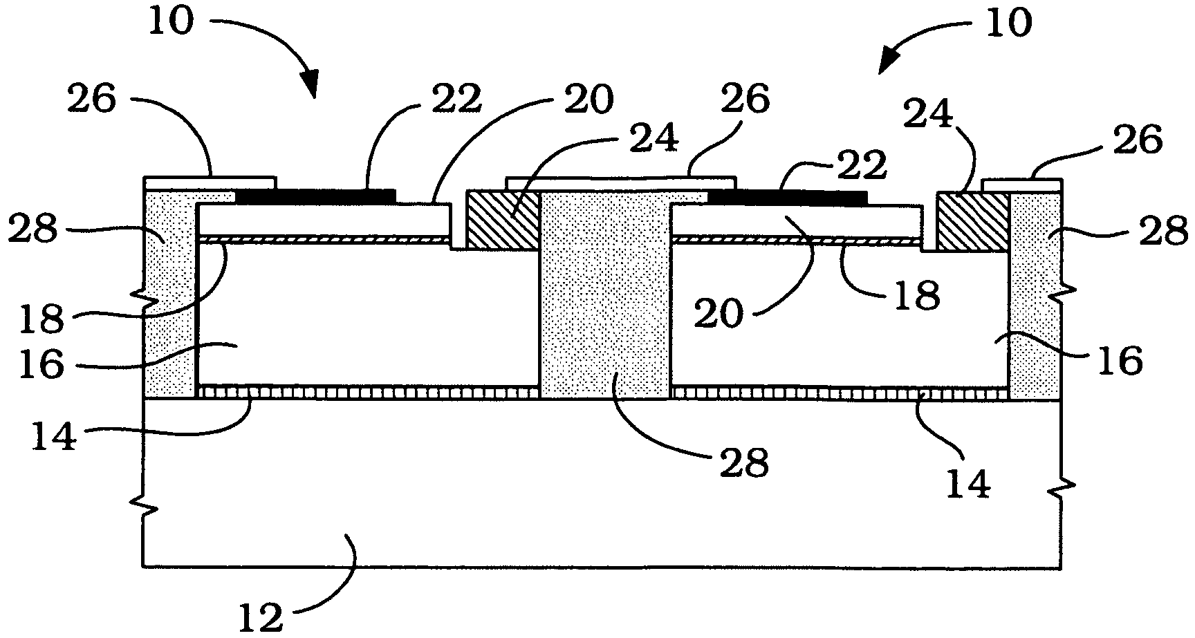
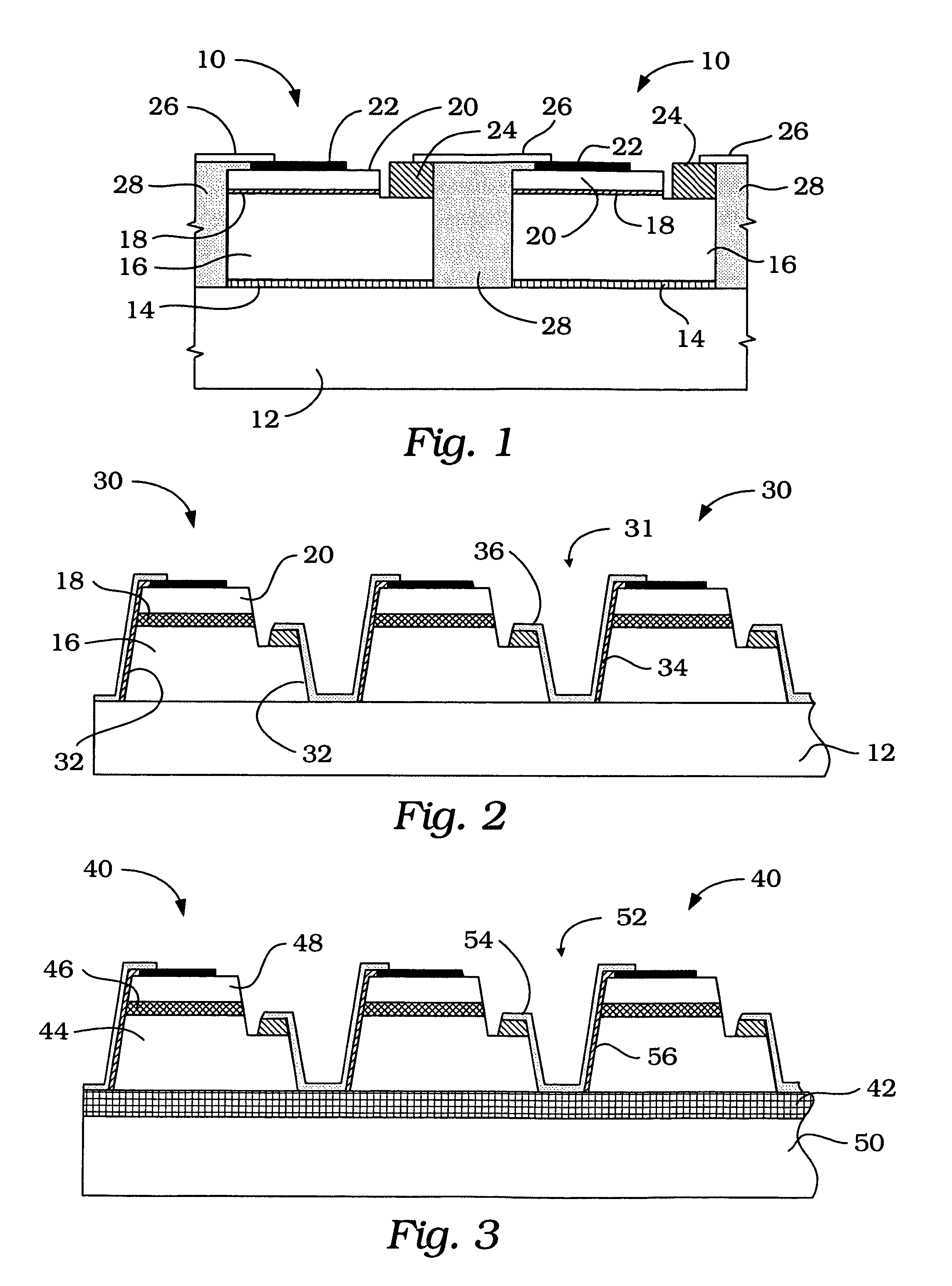
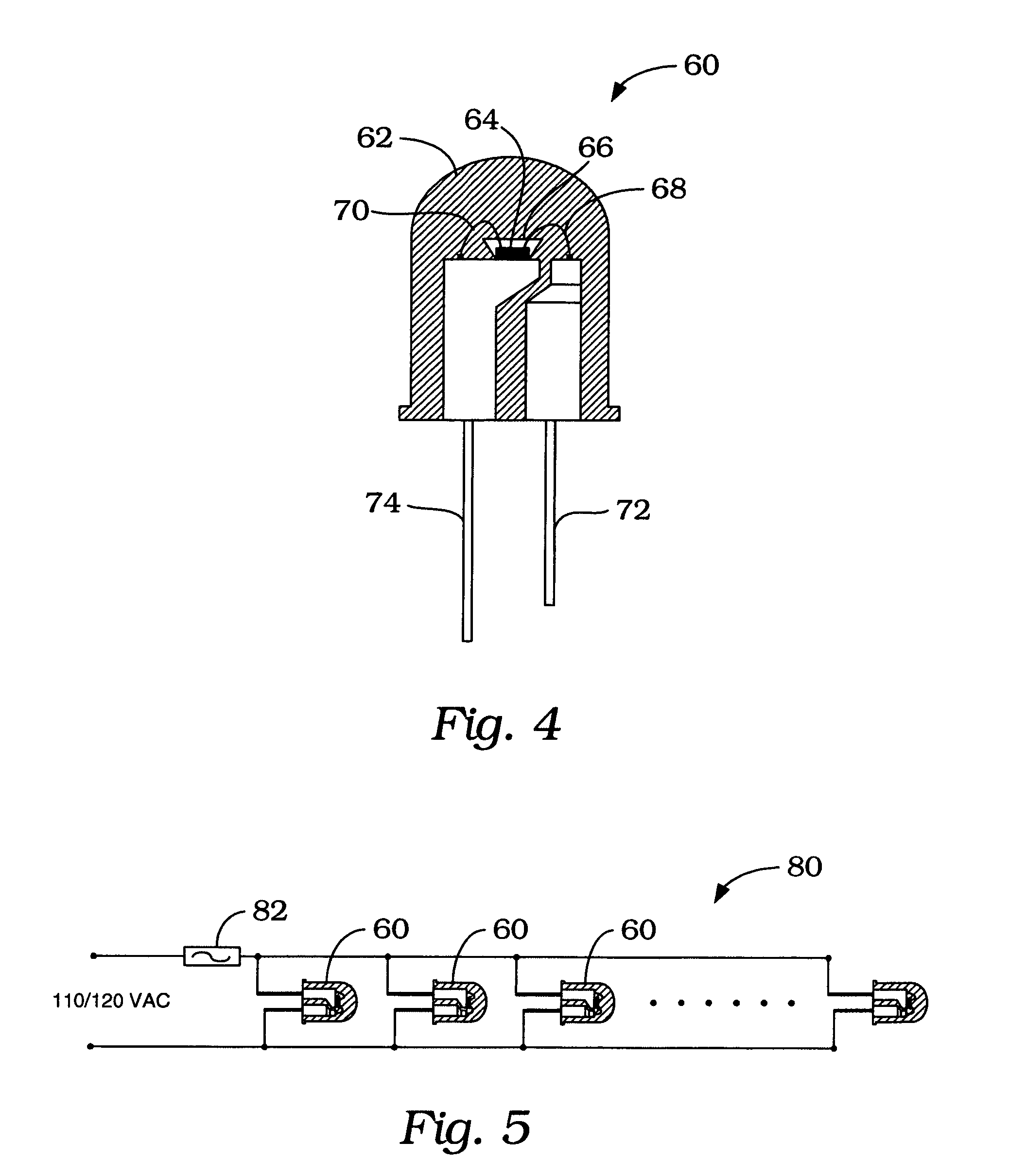
[0018]Referring to FIG. 1, an embodiment of a micro-LED of the present invention based on AlInGaN semiconductor materials is generally indicated by reference numeral 10. Micro-LED 10 may be grown on an insulating sapphire substrate 12 and include a buffer layer 14, n-type semiconductor layer 16, an activation region layer 18 and a p-type semiconductor layer 20. For 120 VAC applications, each micro-LED 10 may have dimensions of approximately 25 μm by 25 μm or similar size, formed by plasma etching down to the insulating substrate 12. A p-contact (anode) 22 and an n-contact (cathode) 24 are formed on the p-type layer 20 and n-type layer 16 separately. A current spreading layer used for the standard broad area LED is generally not required for the micro-LED 10 of the present invention because of the very small size of micro-LED, although its incorporation is also an option.

[0019]The anode and cathode are formed by depositing different metals and then thermally annealing in a different ...


PUM


Abstract

An AC / DC indicator lamp based on an array of micro-LEDs may be powered by a standard high voltage AC or DC power source. The indicator lamp has a low power consumption. The micro-LEDs are serially connected on a substrate with the total device area and power consumption compatible with a standard DC low voltage LED. A plurality of indicator lamps may be connected together in parallel to present a string of indicator lamps.

Description

CROSS-REFERENCE TO RELATED APPLICATION[0001]The present application claims the benefit of provisional application Ser. No. 60 / 649,827, filed Feb. 3, 2005, which is hereby incorporated into the present application by reference.STATEMENT REGARDING FEDERALLY SPONSORED RESEARCH OR DEVELOPMENT[0002]This invention was made in part with the support of the U.S. Government: the U.S. Government has certain rights in this invention as provided for by the terms of Grant DMI-0450314 awarded by the National Science Foundation.FIELD OF THE INVENTION[0003]The present invention relates to a light emitting diode (LED), and more particularly, to an indicator lamp, which includes serially interconnected micro-size LEDs (Micro-LEDs) integrated on a single chip. The resulting indicator lamp may be directly powered by an AC voltage (i.e., 110 / 120V or 220 / 240V power grid) or a high DC voltage without a power transformer.BACKGROUND OF THE INVENTION[0004]Tiny LED indicator lamps have been widely used in elec...

Claims


Application Information

Patent Timeline
Patent Type & Authority Patents(United States)
IPC IPC(8): H01L33/00H01L33/62
CPCH01L27/153F21K9/00H01L33/62H01L2224/48091H01L2224/48247H01L2924/00014H01L2924/181H01L2924/00012
Inventor FAN, ZHAOYANGJIANG, HONGXINGLIN, JINGYU
Owner LED LIGHTING
Learn More