System and method for detecting drifts in calibrated tracking systems

a tracking system and drift detection technology, applied in the field of motion detection and calibration, can solve the problems of harmful outcomes, inaccurate transmission between the tracker's coordinate system and the fixed coordinate system, etc., and achieve the effect of reducing alignment errors

Active Publication Date: 2009-05-19
RESONANT MEDICAL
View PDF20 Cites 61 Cited by
  • Summary
  • Abstract
  • Description
  • Claims
  • Application Information

AI Technical Summary

Benefits of technology

[0010]In another aspect, a method for recalibrating a tracking system to a reference coordinate system includes using a motion-system device to detect alignment errors between the tracker and the fixed coordinate system, and recalibrating (either automatically or manually) the tracker to the fixed coordinate system to reduce or eliminate the alignment errors.
[0016]In another aspect, the invention comprises a method of recalibrating a position-tracking device to a reference coordinate system. The method can include the steps of calibrating a position and orientation of a position-tracking device to a reference coordinate system, using a motion-sensor device to detect alignment errors between the position-tracking device and the fixed coordinate system, and recalibrating the position and orientation of the position-tracking device to the reference coordinate system to reduce the alignment errors.
[0018]In still another aspect, the invention comprises a means for monitoring an object with respect to a first coordinate system. The means comprises; calibrating a position and orientation of a position-tracking device to a reference coordinate system, detecting motion-based alignment errors between the position-tracking device and the fixed coordinate system, and, based on the detected alignment errors, recalibrating the position and orientation of the position-tracking device to the reference coordinate system to reduce the alignment errors.

Problems solved by technology

If, for example, the tracking system is accidentally knocked out of its calibrated position, or if the tracker drifts over time, inaccuracies may be introduced such that the transformation between the tracker's coordinate system and the fixed coordinate system is no longer accurate.
Such misalignments can lead to, for example, inaccurate surgical operations or incorrect delivery of radiation treatments, resulting in potentially harmful outcomes.

Method used


Image

  • System and method for detecting drifts in calibrated tracking systems
  • System and method for detecting drifts in calibrated tracking systems
  • System and method for detecting drifts in calibrated tracking systems

Examples


Embodiment Construction

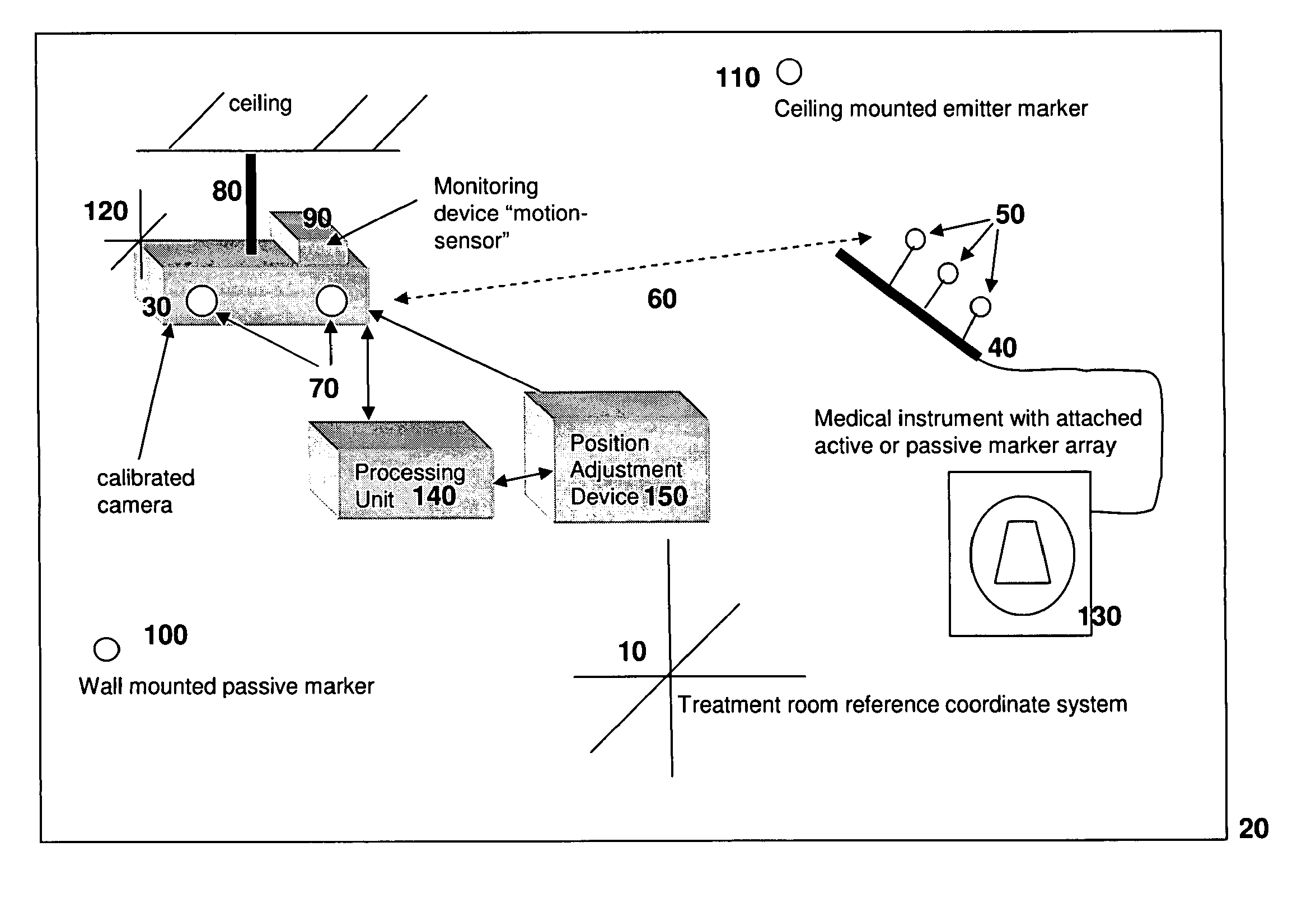
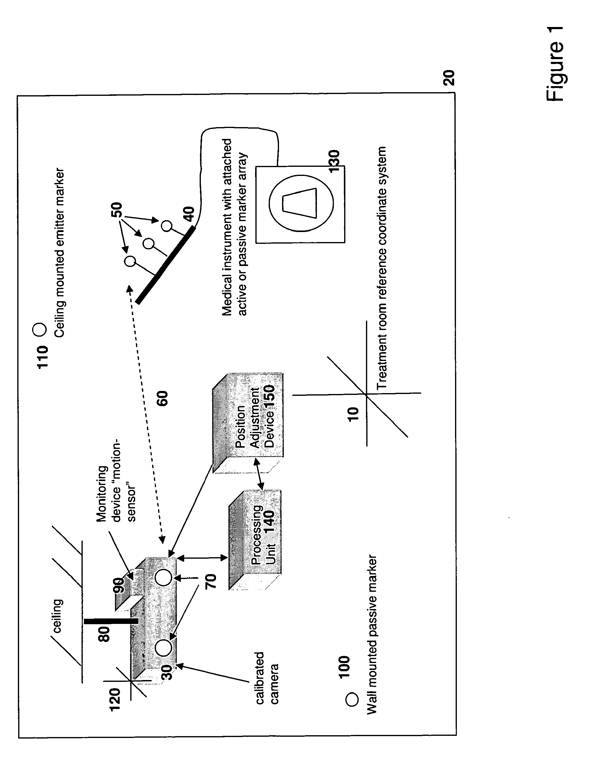
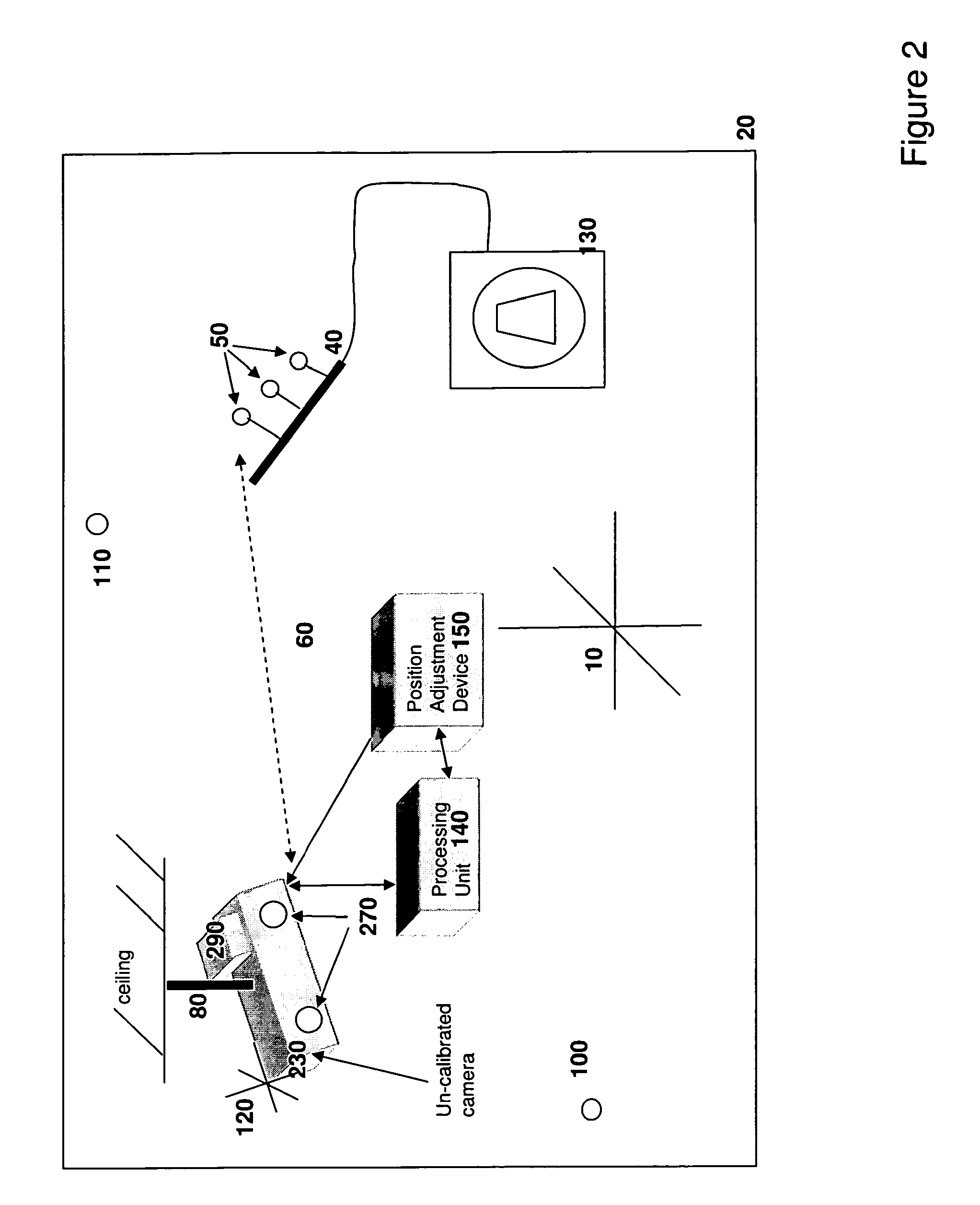
[0022]The invention provides a method and apparatus for monitoring a calibrated position-tracking system for use in tracking the location of features of an object with respect to a reference coordinate system.

[0023]The tracking system may be used to track the location of any feature of an object such as the surface of an object or features such as passive or active markers associated with a medical device, for use in the diagnosis and / or treatment of a patient, where it is advantageous or necessary to accurately locate, and / or record the location of, the medical device.

[0024]To accurately track the location of an object such as a medical device, features such as a marker, or an array of markers, are located within or upon the tracked object to transmit a constant signal, or a discrete repeated signal at regular intervals. The tracked features such as markers may transmit or reflect a signal such as an infrared, magnetic, radio, light, or other electromagnetic signal, that allow as t...


PUM


Abstract

A method and system for detecting drift in calibrated tracking systems used to locate features with respect to one or more coordinate systems allows medical devices to be accurately tracked within a reference coordinate system, and facilitates detection and compensation for changes in the orientation of the tracking system with respect to the coordinate system over time.

Description

CROSS-REFERENCE TO RELATED APPLICATIONS[0001]This application claims priority to and the benefit of U.S. provisional patent application Ser. No. 60 / 704,405, filed Aug. 1, 2005, the disclosure of which is being incorporated herein by reference in its entirety.FIELD OF THE INVENTION[0002]The present invention relates generally to the field of motion detection, and calibration, and more particularly to a system and method for detecting drift in calibrated tracking systems used to locate features, such as surface elements or markers affixed to or embedded within an object, with respect to one or more coordinate systems.BACKGROUND OF THE INVENTION[0003]Spatial tracking systems are used for various procedures such as patient surface feature extraction, surgical navigation, or treatment delivery guidance for patient positioning. One critical performance criterion of such systems is their spatial accuracy—i.e., how accurately the tracking systems identify and track the physical location of ...

Claims


Application Information

Patent Timeline
Patent Type & Authority Patents(United States)
IPC IPC(8): G01S7/40A61B19/00G01S13/88G01S13/06G01S13/00
CPCA61B19/5244G01B7/008G01B11/002G01B11/03G01B15/00G01B17/00G01B21/042A61B2017/00725A61B2019/461A61B2019/4857A61B2019/5255A61B2034/2055A61B34/20A61B2090/061A61B2090/0811
Inventor FALCO, TONY
Owner RESONANT MEDICAL
Why Eureka
Try Eureka